Display device and optical film
a technology of optical film and display device, which is applied in the direction of optical/shielding arrangement, coating, instruments, etc., can solve the problems of insufficient adhesion and residual paste generated by increasing the adhesion of the paste, and achieve the effect of low reflectan
- Summary
- Abstract
- Description
- Claims
- Application Information
AI Technical Summary
Benefits of technology
Problems solved by technology
Method used
Image
Examples
first embodiment
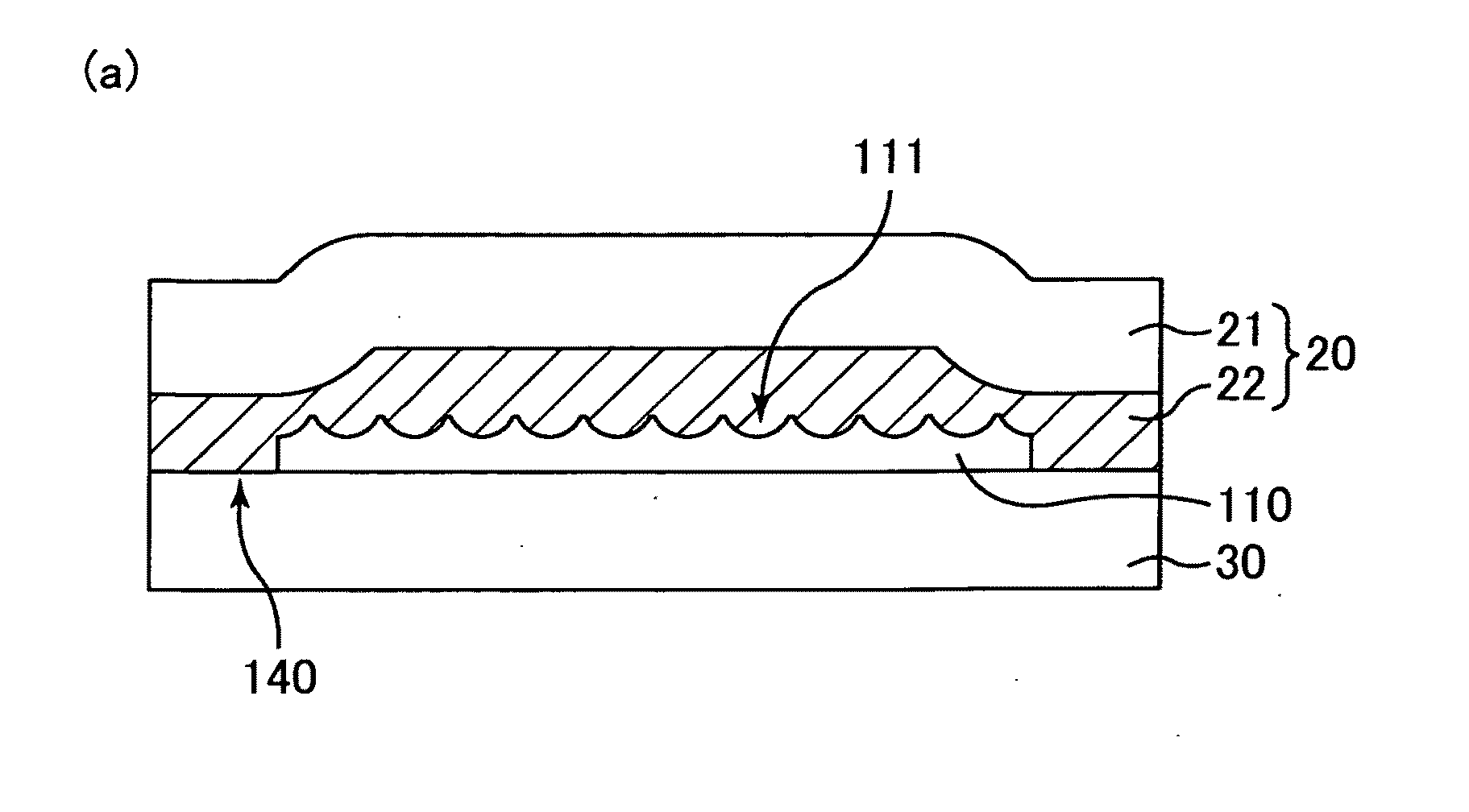
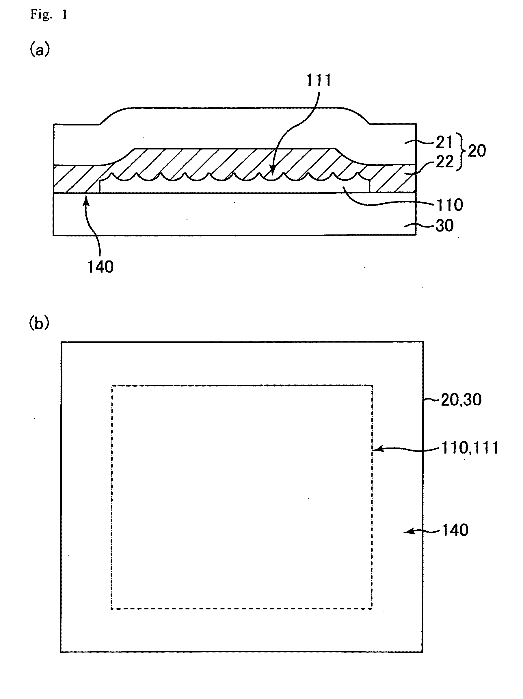
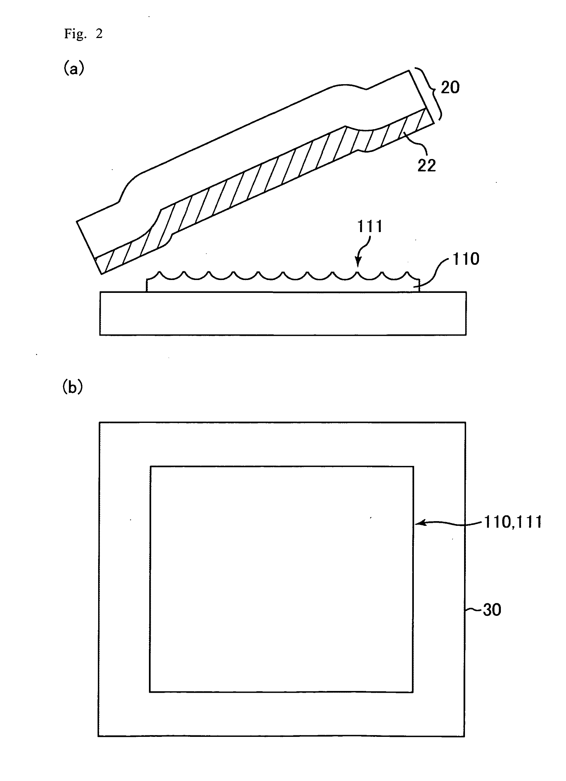
[0043]The display device of the first embodiment, as illustrated in FIGS. 1(a) and 1(b), includes a display panel 30, an anti-reflection film 110 attached to the front surface of the display panel 30, and a protective film 20 peelably attached to the front surface of the anti-reflection film 110. More specifically, the anti-reflection film 110 is attached to a substrate (front surface substrate) on the front surface side of the display panel 30.
[0044]The moth-eye structure 111 is formed in the entire region of the front surface of the anti-reflection film 110. The anti-reflection film 110 is attached in such a manner to at least cover a display region of the display panel 30. The anti-reflection film 110 is smaller than the front surface substrate of the display panel 30, and is not provided at a frame-like peripheral portion located in a non-display region of the front surface substrate.
[0045]The moth-eye structure 111 is provided in such a manner to at least cover the display regi...
second embodiment
[0060]Hereafter, a display device according to a second embodiment will be described. The components in the present embodiment which are the same as those in the first embodiment are designated by the same symbols to avoid the same description.
[0061]The display device of the second embodiment, as illustrated in FIGS. 3(a) and 3(b), includes the display panel 30, an anti-reflection film 210 attached to the front surface of the display panel 30, and the protective film 20 peelably attached to the front surface of the anti-reflection film 210. The anti-reflection film 210 is, more specifically, attached to a substrate on the front surface side (i.e., front surface substrate) of the display panel 30. An optical film comprising the anti-reflection film 210 and the protective film 20 is another aspect of the present embodiment.
[0062]The moth-eye structure 211 is formed on the front surface of the anti-reflection film 210. The anti-reflection film 210 is attached in such a manner to at lea...
example 1
[0083]First, the results of various verification experiments are described.
[0084]A mold 350 for forming a moth-eye structure is produced by utilizing the phenomenon that anodization of an aluminum layer produces nanometric holes in the layer, as illustrated in FIG. 5.
[0085]The anti-reflection film in Example 1 has a moth-eye structure 311 on the surface thereof. The moth-eye structure 311 has fine irregularities, and as shown in FIG. 6, the fine irregularities include a plurality of fine protrusions arranged randomly at intervals that are shorter than the visible light wavelength. In the present example, the distance between the peaks of the adjacent protrusions in the moth-eye structure 311 is 250 nm or shorter.
[0086]Here, the result of the comparison between the reflectance of a conventional low-reflection treatment layer used in a polarizer for common LCDs and the reflectance of the anti-reflection film in Example 1. The conventional low-reflection treatment layer is a low-reflec...
PUM
| Property | Measurement | Unit |
|---|---|---|
| Length | aaaaa | aaaaa |
| Length | aaaaa | aaaaa |
| Optical properties | aaaaa | aaaaa |
Abstract
Description
Claims
Application Information
 - R&D
- Intellectual Property
- Life Sciences
- Materials
- Tech Scout
- Unparalleled Data Quality
- Higher Quality Content
- 60% Fewer Hallucinations
Browse by: Latest US Patents, China's latest patents, Technical Efficacy Thesaurus, Application Domain, Technology Topic, Popular Technical Reports.
© 2025 PatSnap. All rights reserved.Legal|Privacy policy|Modern Slavery Act Transparency Statement|Sitemap|About US| Contact US: help@patsnap.com


