
Method and system for transmitting time in passive optical network

a passive optical network and transmission method technology, applied in the field of communication, can solve the problems of excessive network bandwidth occupancy and excessive protocol workload, and achieve the effects of low hardware cost, small bandwidth occupancy, and high accuracy in time transfer

Active Publication Date: 2012-01-12
IARNACH TECH LTD
View PDF4 Cites 24 Cited by
  • Summary
  • Abstract
  • Description
  • Claims
  • Application Information

AI Technical Summary

Benefits of technology

[0006]In view of this, one of the main purposes of the present invention is to provide a method for time transfer in a passive optical network, which is used to solve the technical problems of complicated processing, excessive protocol workload, and excessive network bandwidth occupancy when using PTP to transfer time in a PON.
[0043]The invention combines the ranging characteristics of PON in time transfer, thereby having high accuracy in time transfer, and the low hardware cost for OLT and ONU, as well as the extremely small bandwidth occupancy due to the usage of a single copy of PON itself to broadcast the time information.

Problems solved by technology

PON is an asymmetric network for delay in the uplink and downlink, complicated flow processing, and excessive protocol workload and excessive network bandwidth occupancy occur when PTP protocol is dealt with in PON.

Method used


Image

  • Method and system for transmitting time in passive optical network
  • Method and system for transmitting time in passive optical network
  • Method and system for transmitting time in passive optical network

Examples


Embodiment Construction

[0047]The preferred examples of the present invention are illustrated below in conjunction with accompanying drawings, and it is appreciated that the preferred examples described herein are only intended for illustration and explanation of the present invention, not for limitation of the present invention.

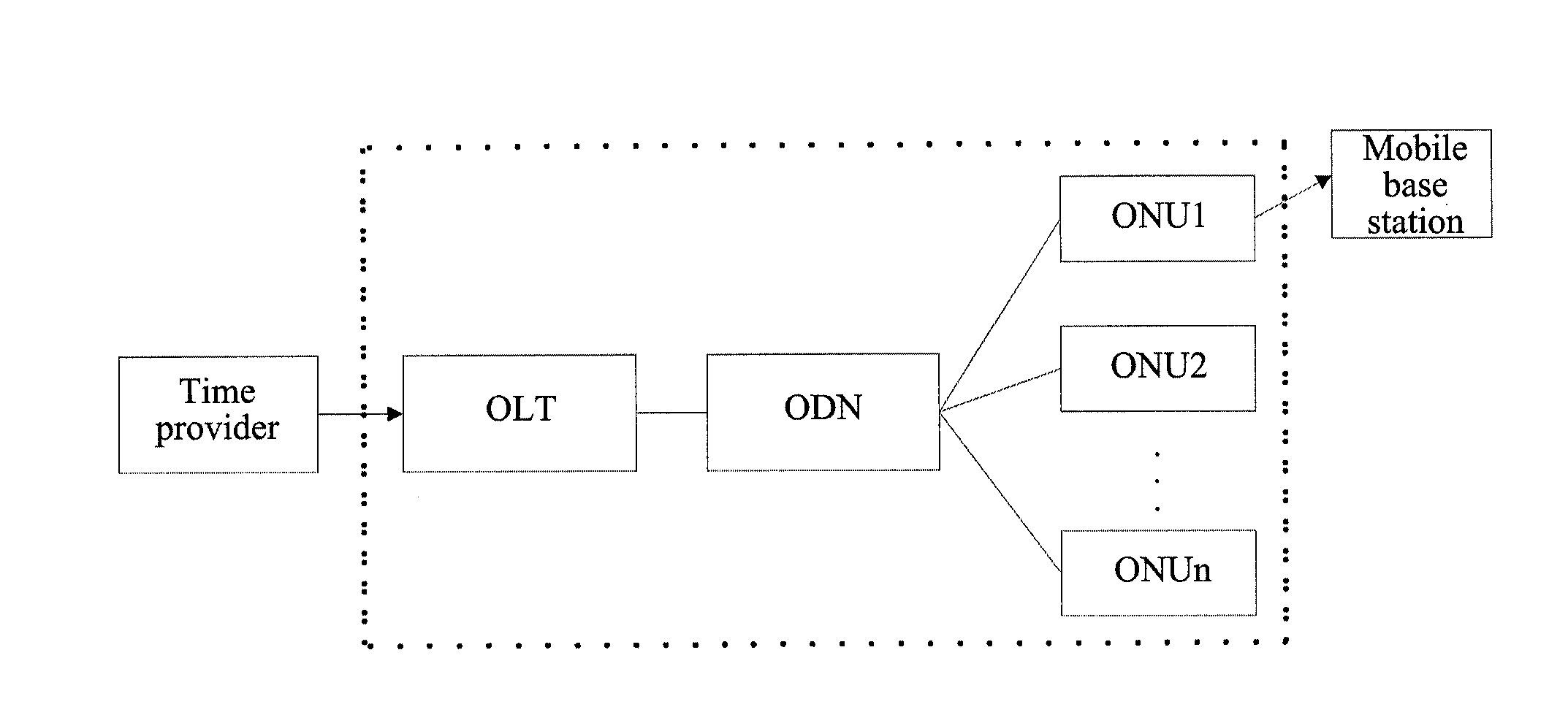
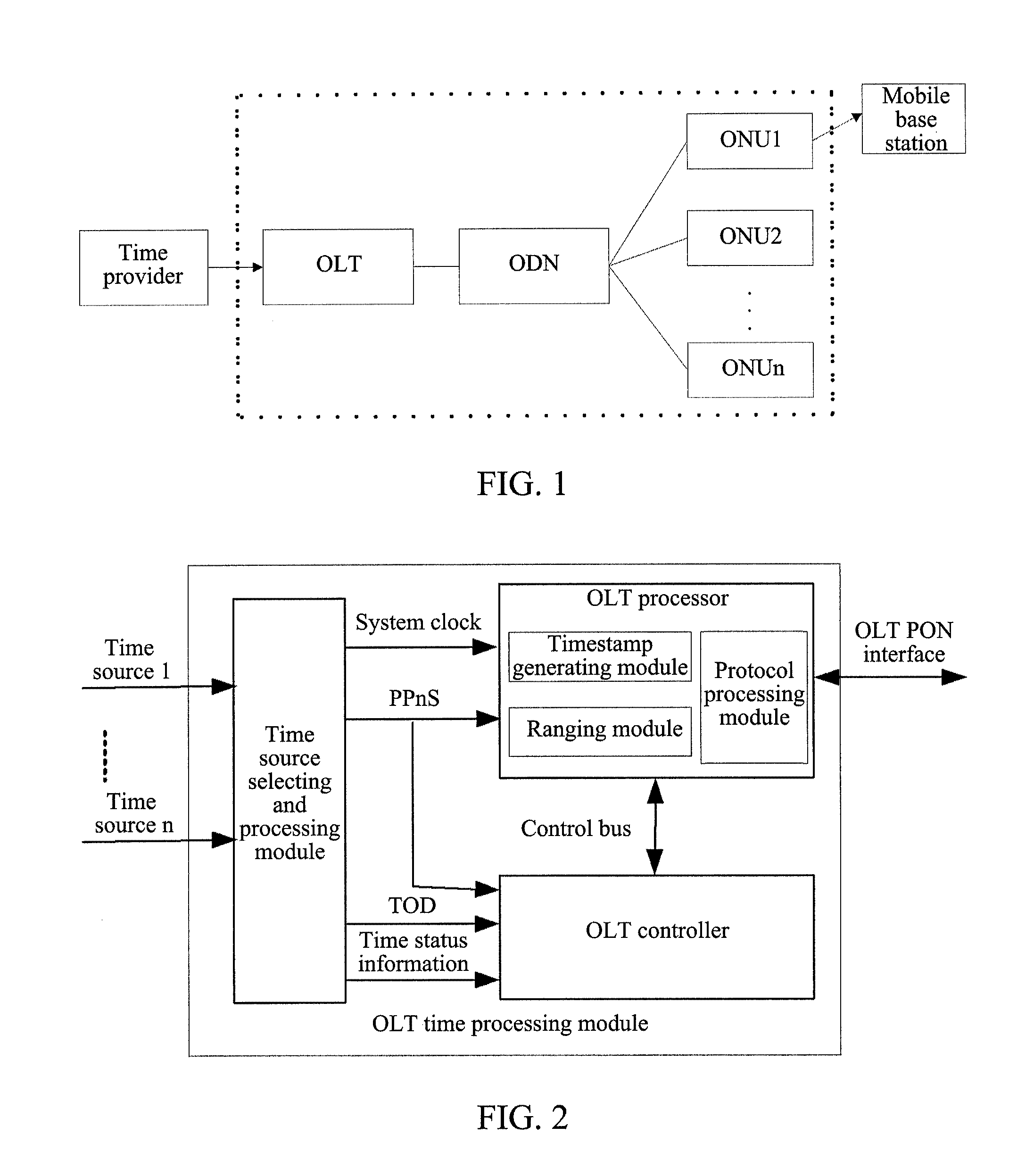
[0048]FIG. 1 is a system structure diagram of PON architecture, and the PON architecture generally consists of three parts of OLT (Optical Line Terminal), ODN (Optical Distribution Network), and ONU (Optical Network Unit). Generally, the distance from OLT to ONU is quite long, and it is up to 20 km in EPON (Ethernet Passive Optical Network) while it is up to 60 km in GPON (Gigabit-Capable PON). The time provider is commonly a mobile time server or a GPS. The part involved in the technical project of the present invention is in the dashed block, and the OLT time processing module in the present invention is located in the OLT, the ONU time processing module is located in the ONU.

[00...


PUM


Abstract

The present invention discloses a method and system for accurate time transfer in PON. An Optical Line Terminal (OLT) ranges Optical Network Units (ONUs) and obtains ranging information, then, triggered by the periodic Pulse per n Second (PPnS), generates a PPnS timestamp based on the local reference counter and the Time of Day (TOD) above second; OLT transmits the ranging information, the periodic PPnS timestamp and TOD to ONUs; ONUs predicts the time of the next second according to said periodic PPnS timestamp, TOD and ranging information, and outputs the corresponding PPnS. The invention is characterized by the combination of the features of PON point to multi-point and PON ranging into its time transfer method, the high accuracy of time transfer, and the low hardware costs for OLT and ONU, as well as the extremely small bandwidth occupancy.

Description

TECHNICAL FIELD[0001]The present invention relates to the communication field of point-to-multipoint passive optical network (PON), and in particular, to one method and system for accurate time transfer in a passive optical network.BACKGROUND OF ART[0002]Optical access technology provides large bandwidth and high reliability, and is a development direction of the access technology. PON is one of the major technologies of optical access, where A / BPON, EPON and GPON have been utilized in large scale.[0003]With the rapid development of data services, the mobility requirement of data access has emerged constantly, and the wired and wireless integration will meet the experiences of users better. With full-service access capability of data, voice and Time Division Multiplex (TDM), PON technology can meet wireless access demand in constant evolution. Especially in the access applications of micro-cells and home base stations, the convergency characteristic of PON makes the entire network c...

Claims


Application Information

Patent Timeline
Patent Type & Authority Applications(United States)
IPC IPC(8): H04J14/00
CPCH04J3/0655H04J3/0682H04Q2011/0088H04Q2011/0079H04Q11/0067
Inventor LU, JIANXINWANG, JINGXUAN
Owner IARNACH TECH LTD
Learn More