Traction mechanism drive having a vibration damper

a technology of vibration damper and traction mechanism, which is applied in the direction of friction dampers, mechanical devices, belts/chains/gearrings, etc., can solve the problems of friction hysteresis, and achieve the effect of increasing the friction moment between the sliding element and the base part and being easy to inser

Inactive Publication Date: 2012-01-12
SCHAEFFLER TECH AG & CO KG
View PDF14 Cites 11 Cited by
  • Summary
  • Abstract
  • Description
  • Claims
  • Application Information

AI Technical Summary

Benefits of technology

[0004]Therefore, the objective is given to provide a traction mechanism drive with a vibration damper that is easier and more economical to produce.
[0005]According to the invention, this objective is solved by a traction mechanism drive, in particular, for an internal combustion engine, containing a vibration damper with a base part and a rotary part that can rotate to a limited extent relative to this base part against the effect of an energy storage device, wherein a friction mechanism with a friction ring with a support element and a sliding element arranged outside of the support element in the radial direction is active between the base part and the rotary part for forming a friction contact relative to a friction surface. According to the invention, the friction ring is produced integrally from the support element and the sliding element, wherein the support element and sliding element are cast one on top of the other and a positive fit is active between these elements in the circumferential direction. Through this integral construction, the friction ring can be managed as a single part. The assembly is therefore simple.
[0006]A material-fit, integral production of the friction ring from components that can be combined with each other in a material fit is here avoided, because this would require a selection from only a limited number of materials. Instead, a positive-fit link between the support element and the sliding element is proposed, so that loading of the friction ring to be transferred only by the material fit can be eliminated. In this way, the selection of materials can be realized essentially freely, so that material pairings that are optimized to their application can be used. For example, the support element could be formed from metal, such as a lightweight metal, for example, aluminum and its alloys, or reinforced, wear-resistant plastics, while the sliding element could be produced from materials with high friction coefficients. In this way, there is only the requirement that one of the components can be processed by an injection-molding process. The second component could be extrusion-coated. In the case of two components that can be injection molded, these could be processed in a two-component injection-molding process.
[0007]The positive fit could be formed such that, in one of the two structural parts—the support element and / or the sliding element—a profiling is provided that is extruded with the component of the other structural part. In this way, the positive fit is provided at least in the rotational direction, for example, by a profiling in the circumferential direction. According to one advantageous embodiment, such profiling could be formed from ribs that are arranged parallel with respect to the rotational axis of the friction ring. Several of these ribs are here distributed across the periphery, for example, arranged on the outer periphery of the support element and are extrusion-coated with the component from plastic material, such as, for example, polyamide of the sliding element. In order to prevent, in particular, a premature detachment of the sliding element, the cross sections of the ribs could have a dovetail-shaped structure.
[0011]The setting of the friction ring could be performed advantageously as a function of the rotational angle between the rotary part and the base part. To this end, the energy storage device formed from a coil spring could be constructed in the radial direction in contact with the inner periphery of the support element, so that, for a rotation of the coil spring, when the rotary part and base part rotate relative to each other, the diameter of the coil spring increases as a function of the rotational angle and thus generates a normal force of the coil force outward in the radial direction on the support element and subsequently on the sliding element, wherein the friction moment between the sliding element and base part is increased. To this end, the friction ring is opened on one side. Advantageously, an elastic compensating link can hold the friction ring closed, so that the friction ring can be easily inserted into the inner periphery of the base part. The elastic compensating link allows an expansion of the friction ring past the assembly diameter as soon as the normal force of the coil spring loads this outward in the radial direction. As a function of the desired friction moment, the friction ring could also be installed in the base part already under biasing.

Problems solved by technology

For rotation between the rotary part and base part due to vibrations introduced into the revolving element of the traction mechanism drive, a friction moment occurs between the friction ring and the base part that causes a damping of these vibrations through the resulting friction hysteresis in combination with the loading of the energy storage device.

Method used


Image

  • Traction mechanism drive having a vibration damper
  • Traction mechanism drive having a vibration damper

Examples


Embodiment Construction

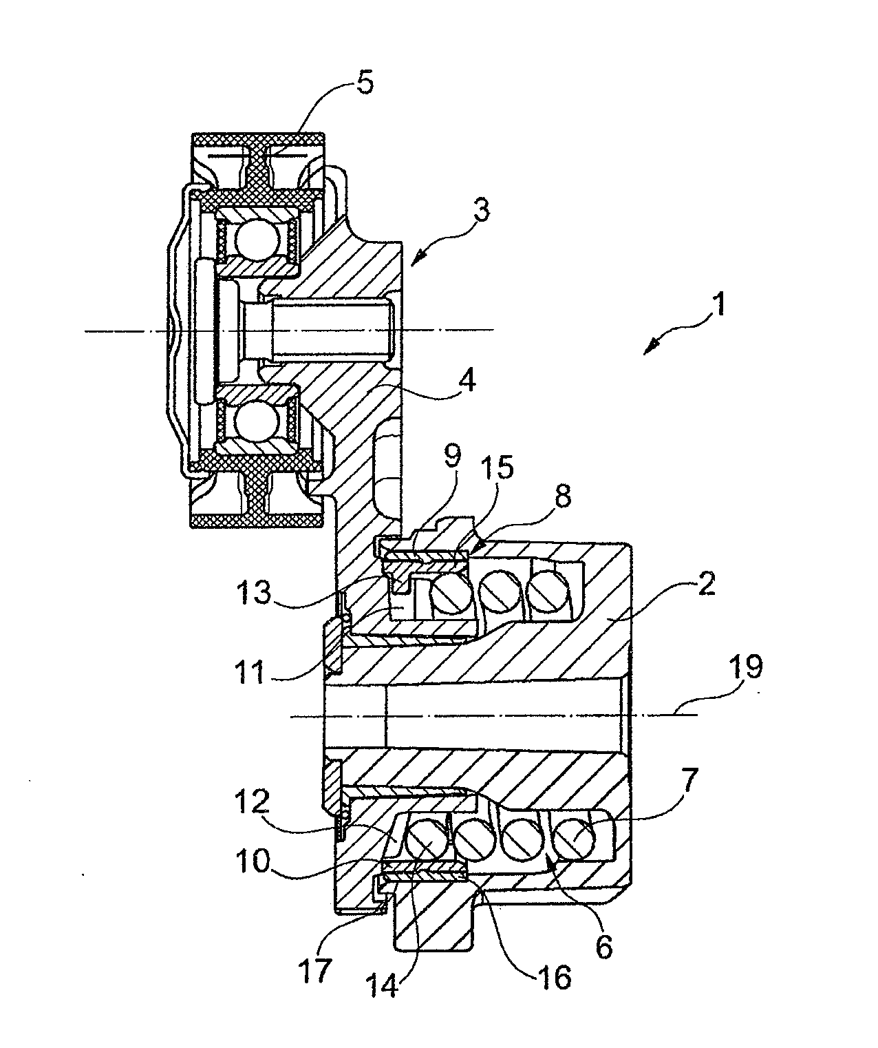
[0015]FIG. 1 shows a vibration damper 1 of a traction mechanism drive not shown in its entirety with a stationary base part 2 attached, for example, to a housing of the internal combustion engine and a rotary part 3 that can be displaced to a limited extent about the rotational axis 19 relative to this base part and is formed here as pivot arm 4 and has the tensioning roller 5 supported so that it can rotate relative to this arm. The tensioning roller 5 engages in the revolving element, for example, a belt, and sets its biasing and damps vibrations introduced into the traction mechanism drive through a pivoting of the pivot arm 4. A force compensating the tension of the revolving element is here applied between the base part 2 and the pivot arm 4 by an energy storage device 6 tensioned between these elements. This energy storage device is formed in the shown embodiment by a coil spring 7 that is tensioned by catch elements at one of its ends locked in rotation with the base part 2 a...


PUM


Abstract

A traction mechanism drive, in particular for an internal combustion engine, including a vibration damper (1) having a base part (2) and a rotary part (3) that can be rotated to a limited extent relative to the base part against the effect of an energy store (6). Between the base part (2) and the rotary part (3), a friction unit (8) having a friction ring (9) formed of a support element (15) and a sliding element (16) arranged radially outside of the support element (15) for forming a friction contact in relation to a friction surface (10) is effective. The friction ring (9) is produced in one piece from the support element (15) and the sliding element (16), and the support element (15) and the sliding element (16) are cast on top of each other. A positive fit (17) is effective between said support element and sliding element in the circumferential direction.

Description

FIELD OF THE INVENTION[0001]The invention relates to a traction mechanism drive, in particular, for an internal combustion engine, containing a vibration damper with a base part and a rotary part that can rotate to a limited extent relative to this base part against the effect of an energy storage device, wherein a friction mechanism with a friction ring is active between the base part and the rotary part.BACKGROUND OF THE INVENTION[0002]Typical constructions of class-forming traction mechanism drives have a tensioning roller that is arranged so that it can pivot relative to the housing of the internal combustion engine and against the effect of an energy storage device; in this way, on one hand, vibrations brought into the traction mechanism drive by pivoting of the tensioning roller are damped and, on the other hand, the tension of the revolving element, for example, a belt, is held constant. For efficient damping of vibrations, it is further advantageous to superimpose a friction...

Claims


Application Information

Patent Timeline
Patent Type & Authority Applications(United States)
IPC IPC(8): F16H7/12
CPCF16F7/06F16H2007/081F16H7/1218
Inventor GILMER, JURGENLIEBEL, THORSTENPROSCH, GERHARDSCHUSTER, CHRISTOPHSINGER, JOHANNTHOMANN, CHRISTINE
Owner SCHAEFFLER TECH AG & CO KG
Why Eureka
Try Eureka