
Method and apparatus for complex time measurements

Active Publication Date: 2012-01-12
ADVANTEST CORP
View PDF1 Cites 16 Cited by
  • Summary
  • Abstract
  • Description
  • Claims
  • Application Information

AI Technical Summary

Benefits of technology

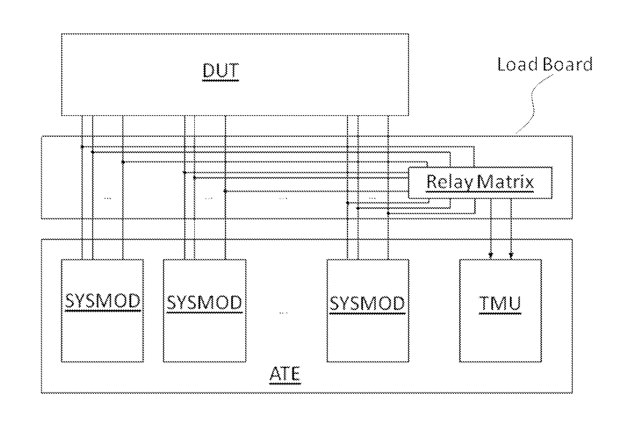
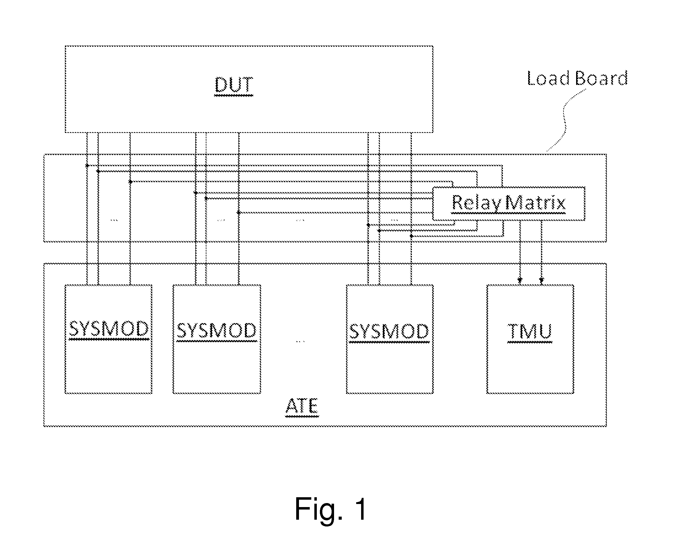
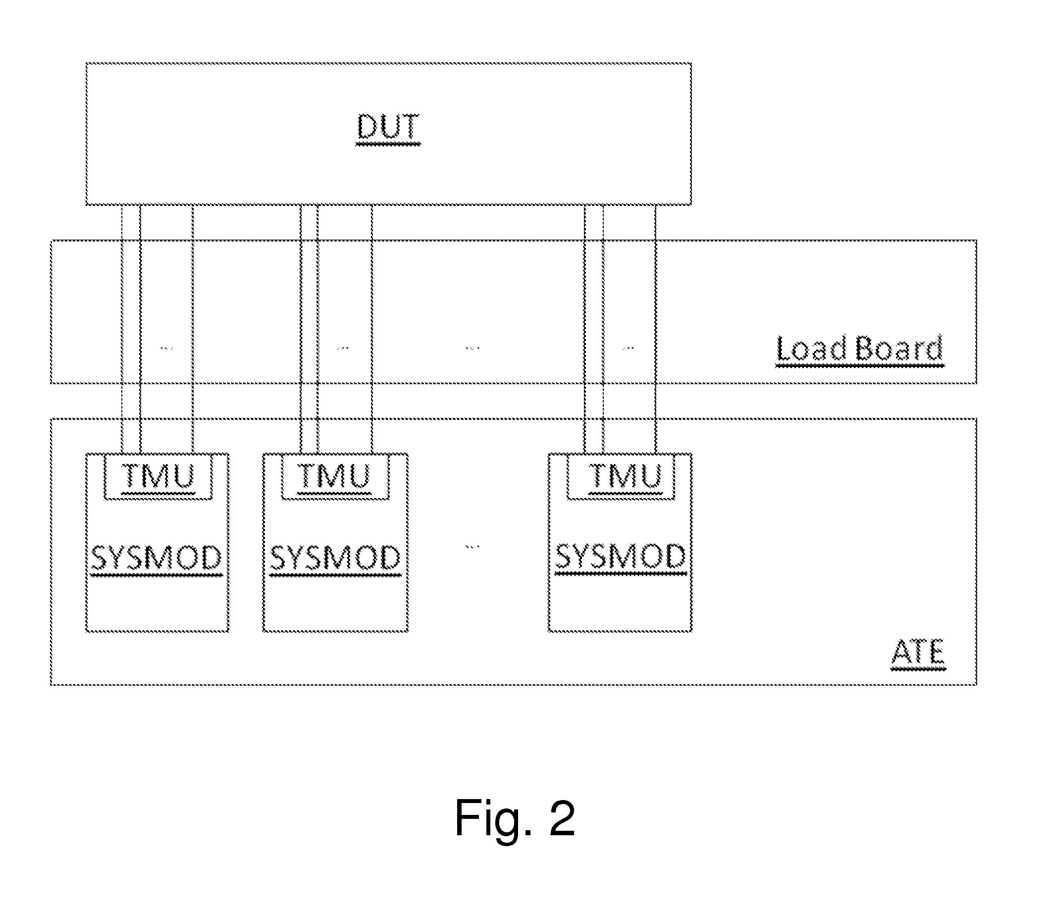
[0019]The method described above may significantly shorten test times required to test a DUT. Even in multi-site applications there is a very limited overhead compared to single-site applications. The add-on in test time may be caused by reading back time stamp values for different DUTs and finally calculating the results. The invention may thus lead to performing complex time measurements while maintaining high test throughput. In addition to test time improvement, the described apparatus may simplify load board design, reduce costs of load boards and improve reliability.
[0023]The described system architecture is not restricted to same hardware across all Global Time Stamping Modules and Global Time Stamping Cores. Time stamp counters may be designed with different resolutions for different groups of signals. Slow signals, e.g. signal comparators of voltage / current (VI) sources, may be recorded with lower resolution than comparators of digital pins. Module firmware or driver software may scale the different resolutions of different hardware to a unified resolution. This way the effort may be scaled and has, for example, the advantage that lower resolution and higher resolution signals can be handled by different devices, which may lead to a further decrease in device complexity and thus in further reduce of testing costs.

Problems solved by technology

These time measurements significantly limit test throughput and drive up testing costs.

Method used


Image

  • Method and apparatus for complex time measurements
  • Method and apparatus for complex time measurements
  • Method and apparatus for complex time measurements

Examples


Embodiment Construction

[0039]The invention will now be described with reference to preferred embodiments which are not intended to limit the scope of the present invention but for exemplifying the invention. Not all of the features and combinations thereof described in the embodiment are necessarily essential to the invention.

[0040]In this specification, a “condition where a member A is connected to a member B” refers to the condition where the member A and the member B are physically connected to each other directly and to the condition where the member A and the member B are connected indirectly via other members that do not affect the electrical connection. Similarly, a “condition where a member C is provided between the member A and the member B” refers to, in addition to the condition where the member A and the member C or the member B and the member C are connected to one another directly, the condition where the members are connected indirectly via other members that do not affect the electrical co...


PUM


Abstract

Apparatus used in an automatic test equipment, comprising a plurality of system modules. Each system module comprises a Time Measurement Unit. The Time Measurement Unit comprises a Global Time Stamping Module. The Global Time Stamping Module comprises a plurality of Global Time Stamping Cores that comprising: an information receiving section for receiving at least two information, an event receiving section for receiving at a Core Input events, an event determining section for determining events of interest from said received events appearing on said Core Input, and an instructing section for instructing a Time Stamp Memory to record a current status of a Time Stamp Counter corresponding to the Clock Information, if an event of interest is determined. The Global Time Stamping Module further comprises a supplying section for supplying said plurality of Global Time Stamping Cores with a common time base.

Description

CROSS REFERENCE TO RELATED APPLICATION[0001]The present application claims the benefit of the filing date of U.S. provisional application No. 61 / 363,515 filed Jul. 12, 2010, the contents of which are incorporated herein by reference.BACKGROUND OF THE INVENTION[0002]1. Technical Field[0003]The invention relates to an automatic test equipment (ATE) for testing integrated circuits.[0004]2. Related Art[0005]In ATE there is a continuously growing demand for measuring complex timing relationships between signals on different pins of a Device Under Test (DUT). This is especially true for testing mixed signal devices. A lot of time measurements have to be done between signals that are rather non-deterministic and are loosely related to stimuli generated by different ATE instruments. These time measurements significantly limit test throughput and drive up testing costs.SUMMARY[0006]In this background, it is an object of one or more embodiments of the present invention to provide an ATE and m...

Claims


Application Information

Patent Timeline
IPC IPC(8): G06F17/40
CPCG01R31/31907
Inventor RICHTER, KLAUSKOEHLDORFNER, ALOISHEIBLER, BERNHARD
Owner ADVANTEST CORP
Learn More