
Storage system and method for changing configuration of cache memory for storage system

a storage system and cache memory technology, applied in the field of storage system and cache memory configuration change, can solve the problem of inability to change and achieve the effect of minimizing the influence of input-output performance and changing the configuration of the cache memory

Inactive Publication Date: 2012-01-12
HITACHI LTD
View PDF6 Cites 21 Cited by
  • Summary
  • Abstract
  • Description
  • Claims
  • Application Information

AI Technical Summary

Benefits of technology

The present invention relates to a storage system and a method for changing the configuration of a cache memory on a storage system. The technical effect of the invention is that it allows for the changing of the cache memory while minimizing the impact on input-output performance relative to a host system. This is achieved by a data transfer control unit that transfers data via the cache memory using a write-after method and switches to a write-through method when the amount of input-output processing with the host system falls below a certain value. The invention also includes a method for preparing for the change in the cache memory configuration, changing the configuration of the cache memory, and restoring the cache memory to its previous state.

Problems solved by technology

If the configuration of a cache memory for a conventional storage system is changed, the storage system needs to be reactivated once; and it is generally impossible to change the configuration of a cache memory while the storage system is active.

Method used


Image

  • Storage system and method for changing configuration of cache memory for storage system
  • Storage system and method for changing configuration of cache memory for storage system
  • Storage system and method for changing configuration of cache memory for storage system

Examples


first embodiment

(1) First Embodiment

(1-1) Configuration of Storage System

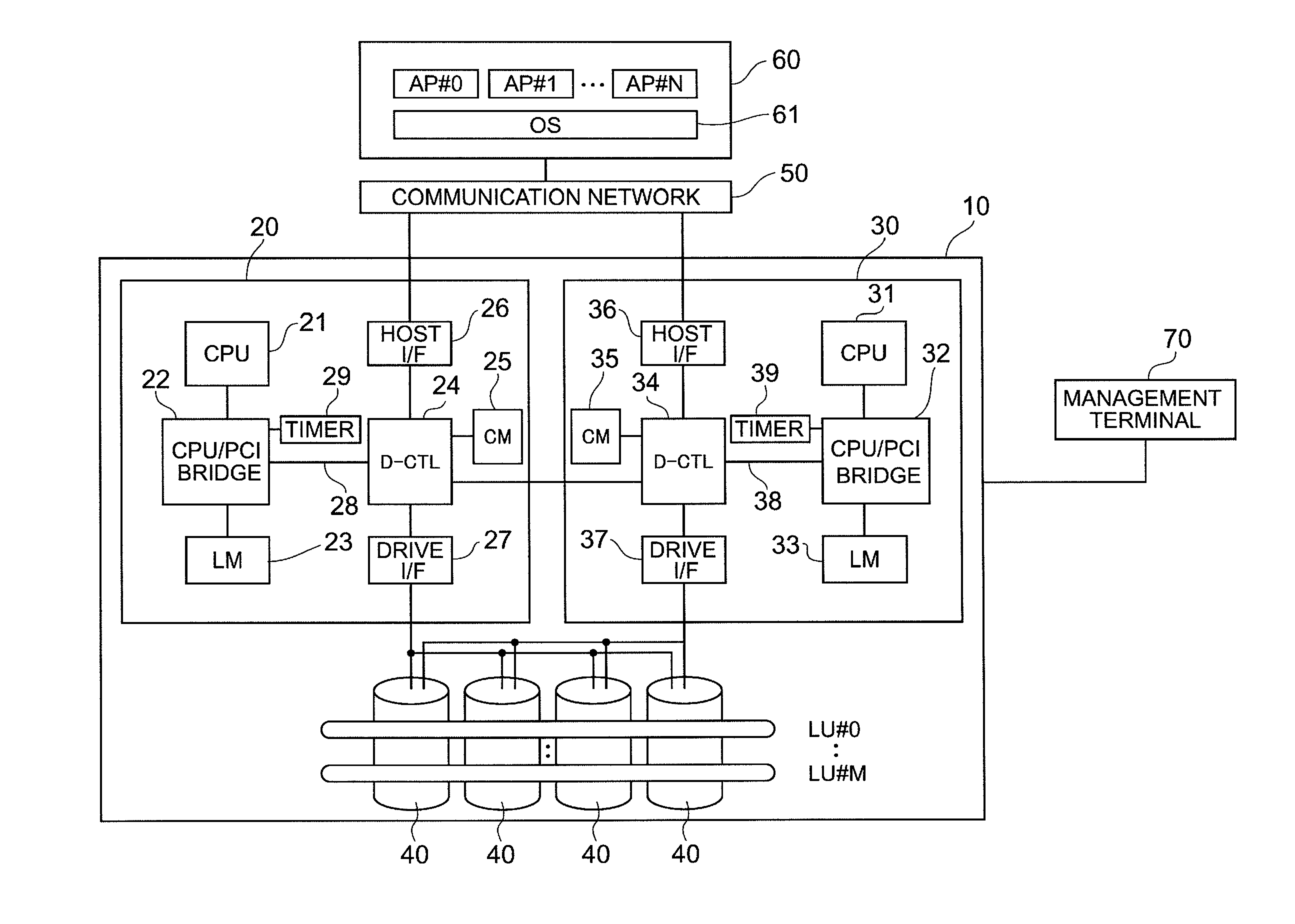
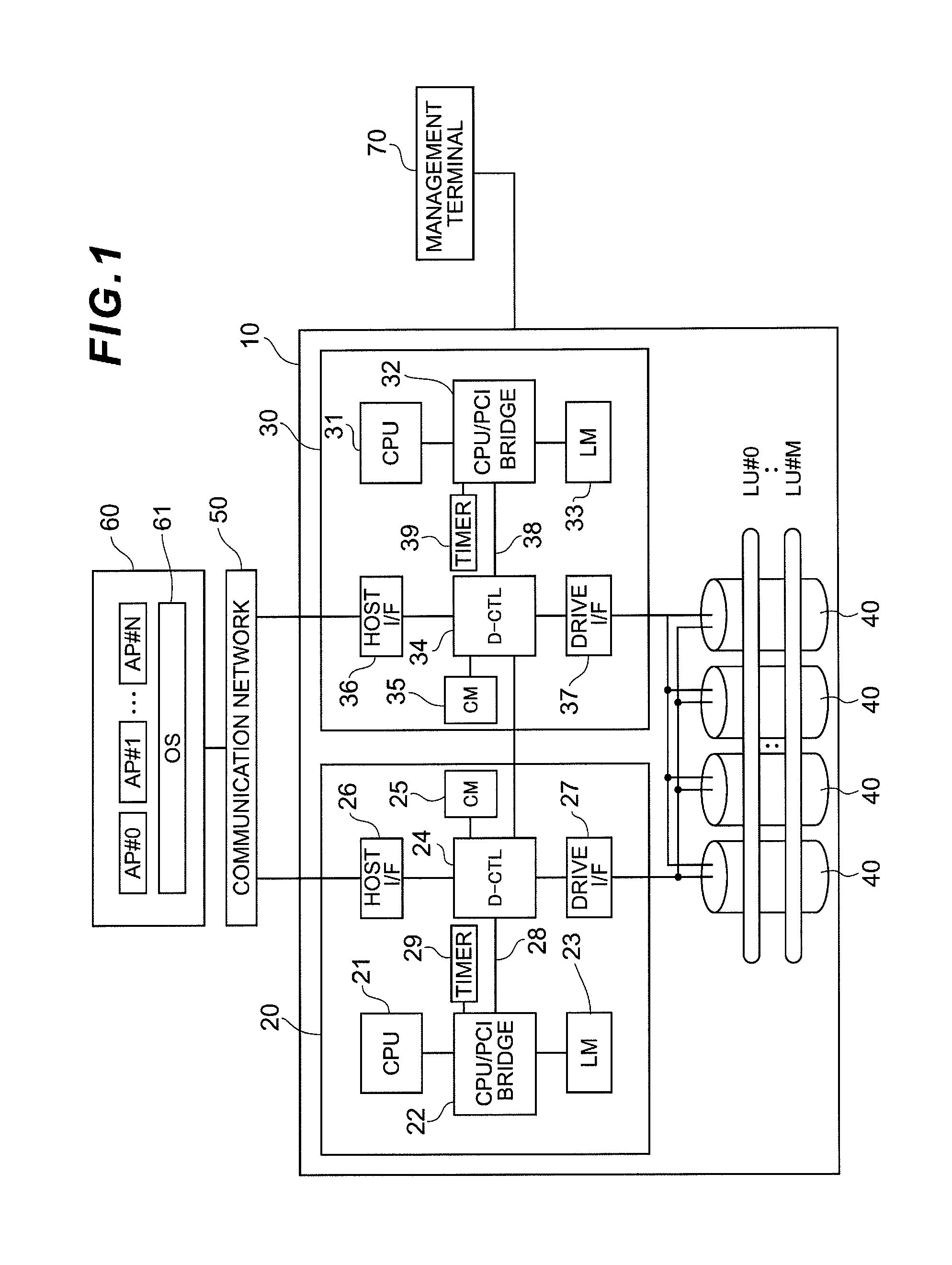
[0030]FIG. 1 shows the main configuration of a storage system 10 according to a first embodiment. The storage system 10 is connected via a communication network 50 to one or more host systems 60. The host system 60 is, for example, a server device, computer, workstation, or mainframe that functions as a host system in the storage system 10. The host system 60 has a plurality of application programs AP #0, AP #1, and so on to AP #N operating on an OS (Operating System) 61. Storage resources provided by the storage system 10 are shared by the plurality of application programs AP #0, AP #1, and so on to AP #N.

[0031]Examples of the communication network 50 include a SAN (Storage Area Network), a LAN (Local Area Network), the Internet, private lines, or a public circuit. If the host system 60 is connected via a SAN to the storage system 10, the host system 60 requests data input-output by blocks, which are data management units of ...

second embodiment

(2) Second Embodiment

[0097]Because the second embodiment is almost the same as the first embodiment, components similar to that of the first embodiment are given the same reference numerals as used in the first embodiment; and the second embodiment will be explained below by focusing on the difference between the first and second embodiments.

(2-1) Method for Changing Configuration of Cache Memory

[0098]FIG. 15 shows an example of steps of a method for changing the configuration of a cache memory according to the second embodiment. Incidentally, since steps in FIG. 15 with the same reference numerals as those in FIG. 14 are almost the same as those in FIG. 14, FIG. 15 will be explained below by mainly focusing on the difference between the steps in FIG. 14 and the steps in FIG. 15.

[0099]In the second embodiment, processing from step SP5 to SP7 is different from that in the first embodiment. In the second embodiment, the data transfer control unit 24 continues to use the write-after me...


PUM


Abstract

The configuration of a cache memory can be changed while minimizing the influence over input-output performance with a host system on the active storage system.A data transfer control unit transfers data via a cache memory by a write-after method; and as triggered by an event where an amount of input to and output from an object area in the cache memory falls below a certain value, the data transfer control unit switches from the write-after method to a write-through method and then transfers data via the cache memory. Subsequently, as triggered by an event where there is no longer any input to and output from the object area in the cache memory, a processor changes the configuration of the cache memory relating to the object area.

Description

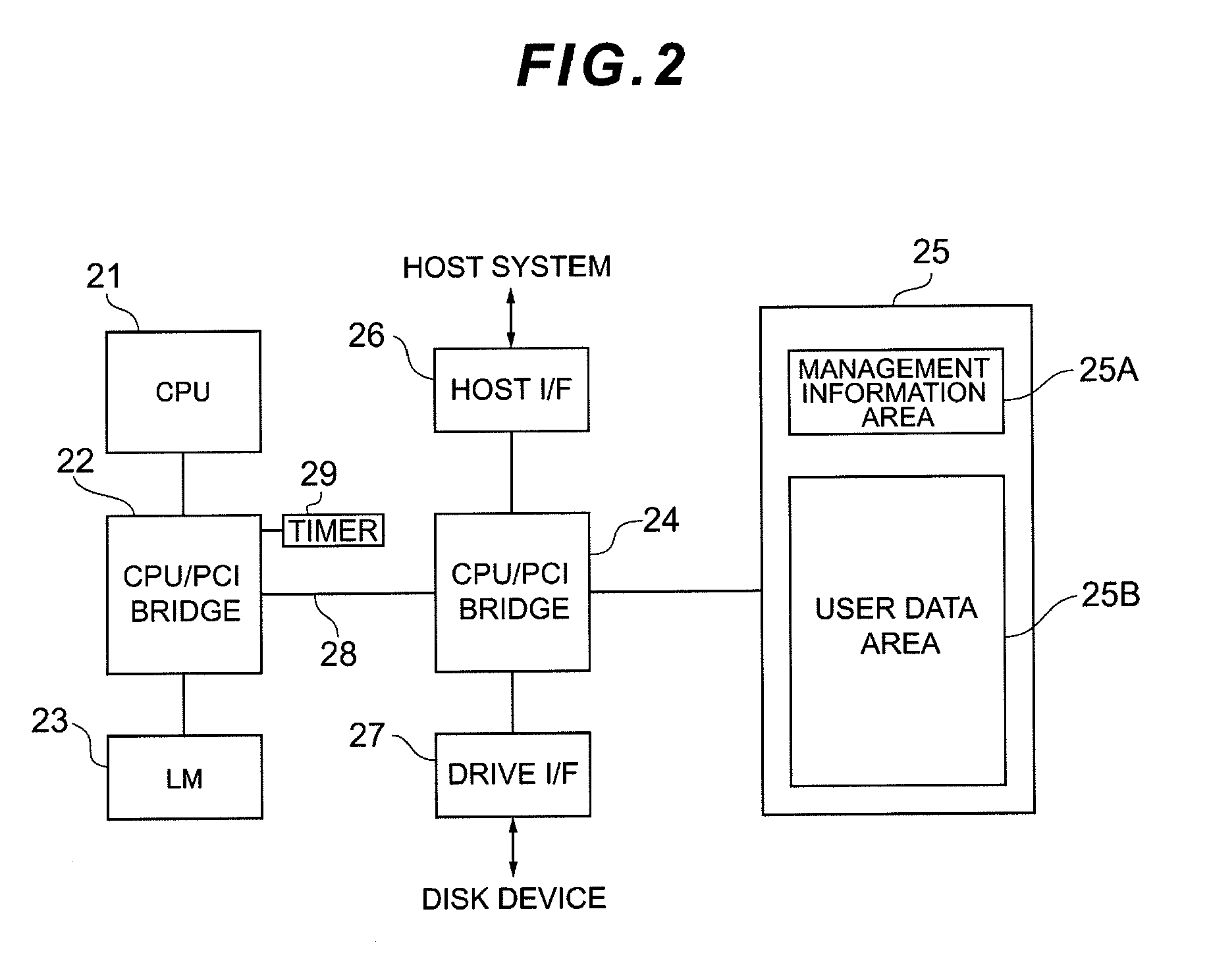
TECHNICAL FIELD[0001]The present invention relates to a storage system and a method for changing the configuration of a cache memory on a storage system. Particularly, the invention is ideal for use in a storage system relating to a technique of changing the configuration of the cache memory.BACKGROUND ART[0002]In recent years, storage consolidation by which storage units distributed and located in each server are consolidated in one place and the consolidated storage units are connected to a group of servers via a storage-only network such as a SAN (Storage Area Network) has become widespread. As an operation form of storage consolidation, a case where a storage system shared by a plurality of application programs or contents has been increasing. The storage system is equipped with, for example, a disk array apparatus. The disk array apparatus is configured by placing many disk drives in arrays and constructed based on, for example, RAID (Redundant Array of Independent Inexpensive ...

Claims


Application Information

Patent Timeline
Patent Type & Authority Applications(United States)
IPC IPC(8): G06F12/08
CPCG06F12/0804G06F2212/601G06F12/0866
Inventor HIGASHIJIMA, NAOKIMATSUI, YUKO
Owner HITACHI LTD
Learn More