Separation of a Sour Syngas Stream

Inactive Publication Date: 2012-01-19
AIR PROD & CHEM INC
View PDF1 Cites 18 Cited by
  • Summary
  • Abstract
  • Description
  • Claims
  • Application Information

AI Technical Summary

Problems solved by technology

However, such processes result in a crude syngas stream containing, in addition to H2 and CO, also CO2 and H2S.
After separating the H2S and CO2 from the syngas, it may not be practical or permissible to store the H2S with the CO2.

Method used


Image

  • Separation of a Sour Syngas Stream
  • Separation of a Sour Syngas Stream
  • Separation of a Sour Syngas Stream

Examples


Example

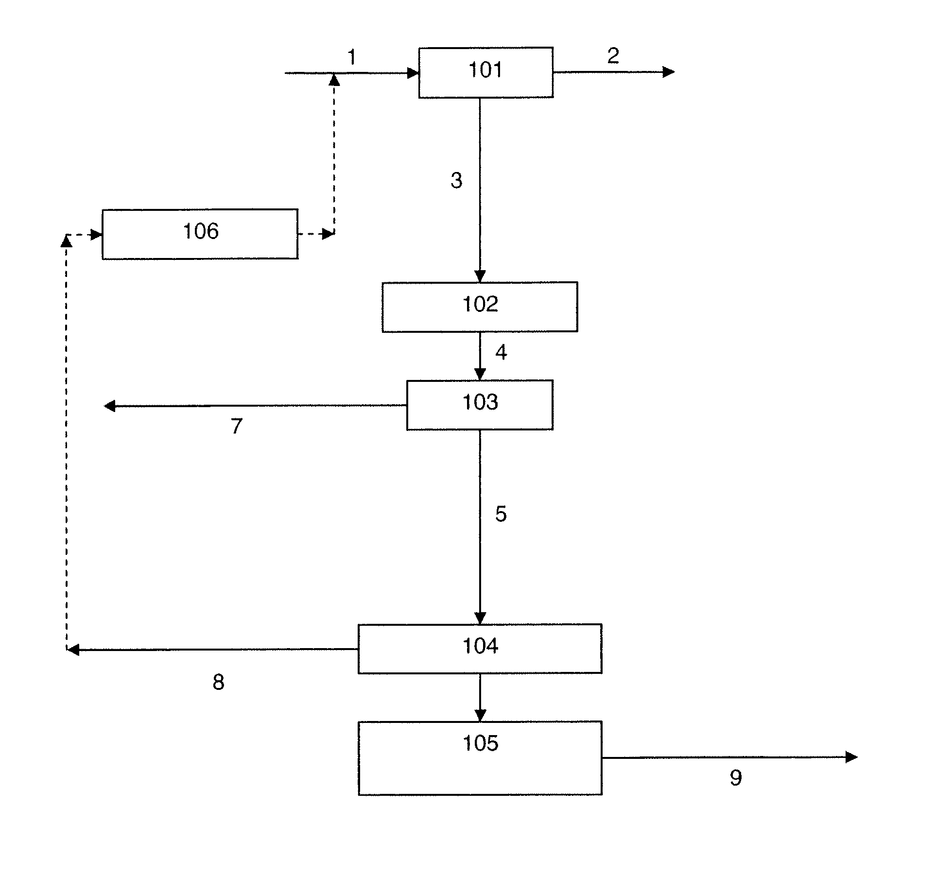
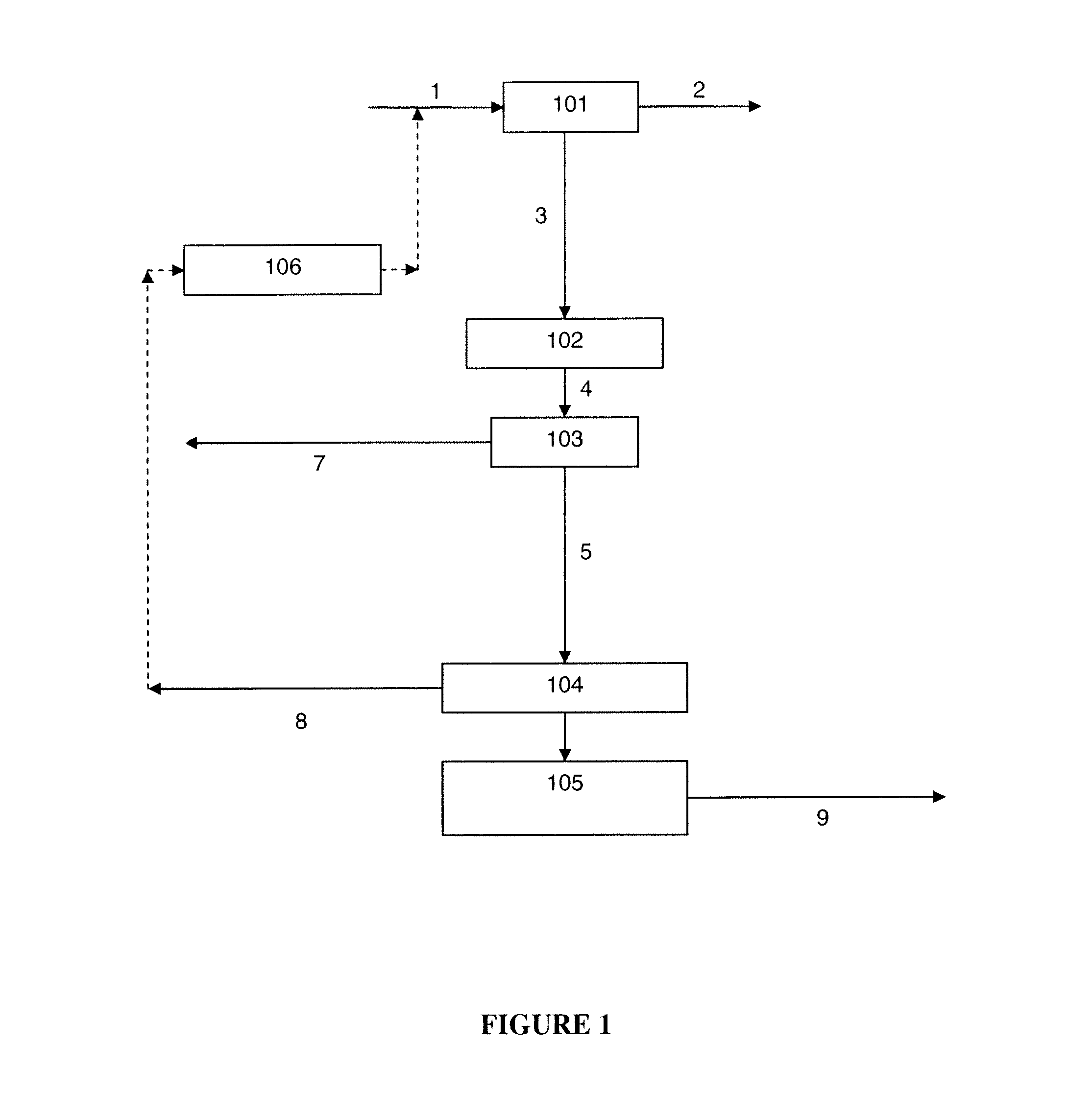
[0092]Thus, in one embodiment (hereinafter, the “first embodiment”) of the method of the present invention:[0093]the feed stream is introduced into the H2 / CO-PSA system;[0094]the H2 / CO-PSA system separates the feed stream to provide the H2 / CO product stream and a stream enriched in CO2 and H2S;[0095]the H2S removal system processes said stream enriched in CO2 and H2S to provide a stream enriched in CO2 and depleted in H2S; and[0096]the further separation system separates said stream enriched in CO2 and depleted in H2S to provide the CO2 product stream and a stream comprising H2 or H2 and CO.

[0097]Further preferred features of this first embodiment, such as use of the H2S removal system to remove also water, use of a sour-PSA system as the H2S removal system, uses of the H2S enriched stream also produced by the sour-PSA system, possible uses of the stream comprising H2 or H2 and CO, preferred compositions of the various stream, and so forth, will be apparent from the forgoing general...

Example

[0099]In another embodiment (hereinafter, the “second embodiment”) of the method of the present invention:[0100]the feed stream is introduced into the H2S removal system;[0101]the H2S removal system processes the feed stream to provide a stream depleted in H2S;[0102]the H2 / CO-PSA system separates said stream depleted in H2S to provide the H2 / CO product stream and a stream enriched in CO2 and depleted in H2S; and[0103]the further separation system separates said stream enriched in CO2 and depleted in H2S to provide the CO2 product stream and a stream comprising H2 or H2 and CO.

[0104]Further preferred features of this embodiment will again be apparent from the forgoing general description of the method.

[0105]As compared to the aforementioned first embodiment, the method according to this second embodiment has certain advantages and disadvantages. The disadvantages are that: there are, if a sour-PSA system is used as the H2S removal system, two PSA systems in the H2 / CO product stream p...

Example

[0106]In another embodiment (hereinafter, the “third embodiment”) of the method of the present invention:[0107]the feed stream is introduced into the H2 / CO-PSA system;[0108]the H2 / CO-PSA system separates the feed stream to provide the H2 / CO product stream and a stream enriched in CO2 and H2S;[0109]the further separation system separates said stream enriched in CO2 and H2S to provide a stream further enriched in CO2 and H2S and a stream comprising H2 or H2 and CO; and[0110]the H2S removal system processes said stream further enriched in CO2 and H2S to provide the CO2 product stream.

[0111]Further preferred features of this embodiment will again be apparent from the forgoing general description of the method.

[0112]As compared to the first embodiment, the method according to this third embodiment also has certain advantages and disadvantages. The advantages are that, where a H2S removal system is used that also produces an H2S enriched stream, the H2S concentration in this H2S enriched ...


PUM


Abstract

A feed stream, comprising hydrogen sulphide (H2S), carbon dioxide (CO2), hydrogen (H2) and, optionally, carbon monoxide (CO), is separated into at least a CO2 product stream and an H2 or H2 and CO product stream. The stream is separated using a pressure swing adsorption system, an H2S removal system and a further separation system, which systems are used in series to separate the stream. The method has particular application in the separation of a sour (i.e. sulphur containing) syngas, as for example produced from the gasification of solid or heavy liquid carbonaceous feedstock.

Description

BACKGROUND OF THE INVENTION[0001]The present invention relates to a method for separating a feed stream, comprising hydrogen sulphide (H2S), carbon dioxide (CO2), and one or both of hydrogen (H2) and carbon monoxide (CO), into at least a CO2 product stream and an H2 or H2 and CO product stream. The invention has particular application in the separation of a sour (i.e. sulphur containing) syngas, as for example may be obtained from the gasification of solid or liquid carbonaceous feedstock, to obtain: a CO2 rich product stream suitable for geological storage; an H2 or H2 and CO product stream suitable for use in a chemicals plant or refinery, or as fuel for a gas turbine; and, optionally but preferably, an H2S enriched stream that can be further processed, e.g. in a Claus unit or other suitable sulphur recovery system, in order to convert to elemental sulphur the H2S contained therein.[0002]It is well known that streams comprising H2 and CO can be produced via gasification of solid o...

Claims


Application Information

Patent Timeline
IPC IPC(8): B01D53/02B01D53/22C01B32/50
CPCB01D53/047B01D53/229B01D2256/16B01D2256/20B01D2256/22Y02C10/08B01D2257/504B01D2259/40052B01D2259/40069B01D2259/4065B01D2257/304Y02C20/40
Inventor WRIGHT, ANDREW DAVIDWHITE, VINCENTFOGASH, KEVIN BOYLEKLOOSTERMAN, JEFFREY WILLIAMHUFTON, JEFFREY RAYMONDSCHAFFER, CHARLES LINFORD
Owner AIR PROD & CHEM INC
Why Eureka
Try Eureka