Evaporation chamber, intermediate chamber, and method

a technology of intermediate chambers and evaporators, which is applied in the direction of gas purification by liquid washing, medical atomisers, heating types, etc., can solve the problems of large floats covering a considerable portion of water surface, low power consumption during operation, and other known methods that have not been accepted, etc., to achieve convenient and cost-effective use, reduce the size of the surface area, and simplify the assembly and disinfection of the intermediate chamber

Inactive Publication Date: 2012-01-19
SELEON
View PDF3 Cites 20 Cited by
  • Summary
  • Abstract
  • Description
  • Claims
  • Application Information

AI Technical Summary

Benefits of technology

[0019]A level valve can be realized in an easy and cost-efficient manner, for instance, with a valve actuated by a float.
[0020]The humidification of gas in the space between a trough and the bottom of an intermediate chamber is advantageous because the surface of a water film standing in the trough is not reduced by a float. Moreover, the water film in the trough may be thinner as compared to the height of the set water level in the intermediate chamber because the water film need not produce a buoyancy for a float.
[0021]By using a compensating pipe in addition to a liquid outlet the continued flow of water and the pressure compensation are locally separated, so that the thickness of the water film in the trough is maintained more exactly.
[0022]By the guidance of the float by the compensating pipe the compensating pipe can advantageously assume an additional function. This simplifies the assembly and the disinfection of the intermediate chamber because the intermediate chamber need not comprise any additional guiding means and, therefore, has altogether fewer edges and a smaller surface area. In addition, the float is not disturbed by rising air bubbles.
[0023]Due to the fact that the upper surface of the float is inclined downwards in the outward direction it is avoided in a surprisingly simple manner that water accumulates on the float.

Problems solved by technology

Also, the power consumption is lower during the operation because only a small part of the casing, in the proximity of the heater, and not the whole storage tank has to be maintained at the operating temperature.
It is cost-efficient, easy to mount, may be produced from bio-compatible material and does not permit any substantial deviations of the filling level.
Other known methods have not been able to gain acceptance for this application owing to the strict regulations, especially the Medicinal Products Act (Medizinproduktgesetz—MPG), the Ordinance of Medical Devices Vigilance (Medizinprodukt-Sicherheitsplanverordnung—MPSV) and the Medical Devices Operator Ordinance (Medizinprodukt-Betreiberverordnung—MPBetreibV), and owing to costs, service life, exchangeability, cleaning or sterilisability of the components, maintenance, installation work and measurement position.
The disadvantage is that the relatively large floats cover a considerable portion of the water surface and, moreover, require a certain immersion depth.

Method used


Image

  • Evaporation chamber, intermediate chamber, and method
  • Evaporation chamber, intermediate chamber, and method

Examples


Embodiment Construction

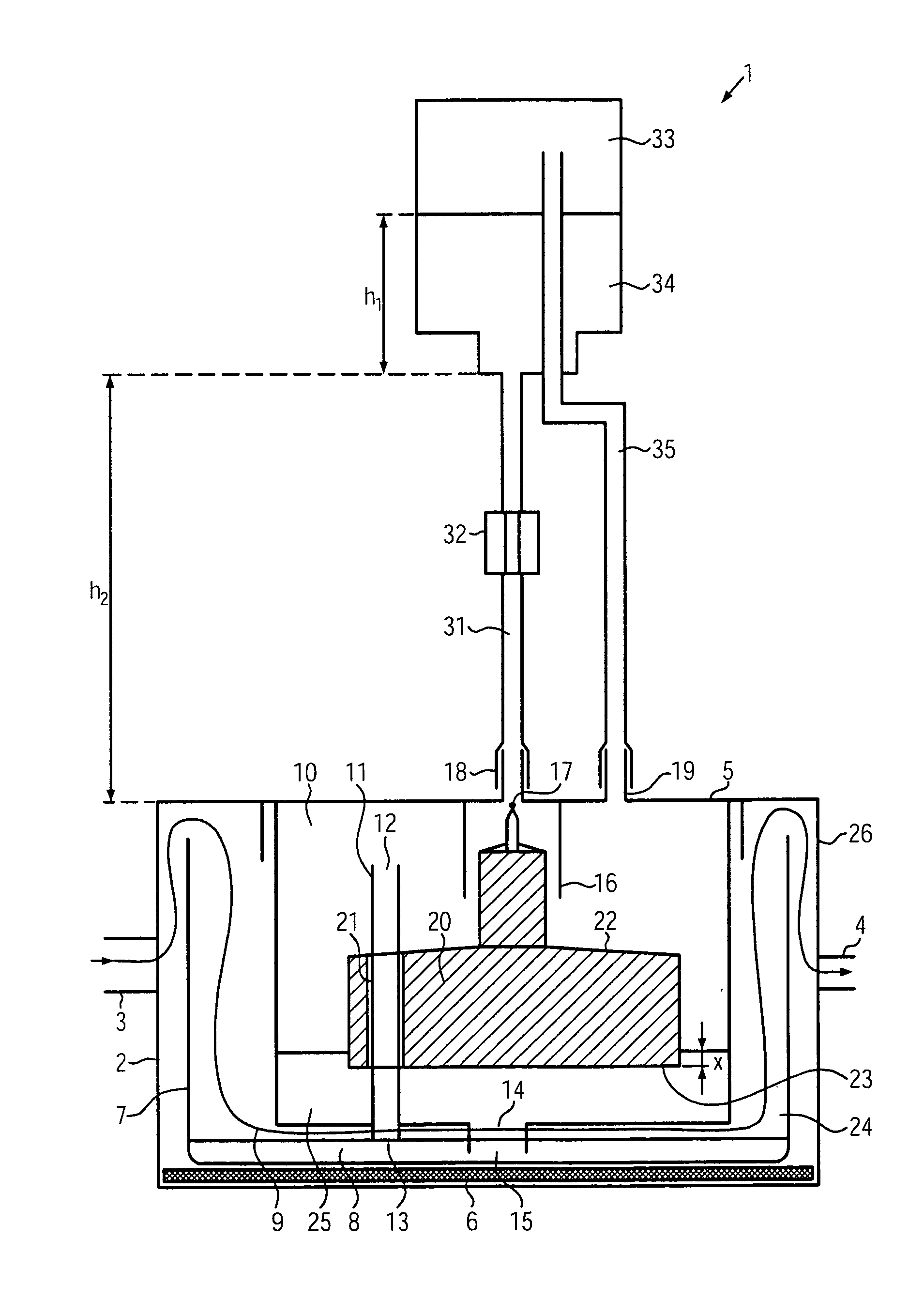
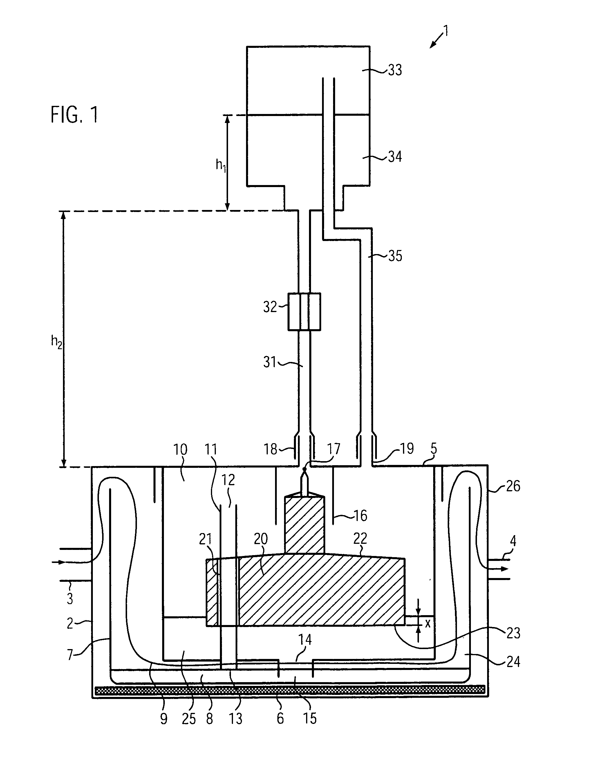
[0057]The respiratory gas humidifier 1 according to the invention shown in FIG. 1 is substantially comprised of an evaporation chamber 2 and of a sterilized water container 33 which is connected by a water conduit 31 and a compensating conduit 35 to a water connection 18 and a compensation connection 19 of the evaporation chamber 2. The water conduit 31 is typically formed of a flexible, transparent plastic tube and can be closed by a roller clamp 32.

[0058]The evaporation chamber 2 comprises a casing 26, a lid 5, a heating plate 6, a trough 7 as well as an intermediate chamber 10. In FIG. 1, the casing 26 forms a gas inlet 3 on the left and a gas outlet 4 on the right. The air flow 9 from the gas inlet 3 to the gas outlet 4 across a water film 8 is drawn in as well. At its bottom the intermediate chamber 10 is provided with a water outlet 14 having a lower end 15. Moreover, a compensating pipe 11 is mounted on the bottom of the intermediate chamber 10 perpendicular to the bottom, i....


PUM

PropertyMeasurementUnit
partial pressureaaaaaaaaaa
pressureaaaaaaaaaa
angleaaaaaaaaaa

Abstract

An evaporation chamber comprises a trough and an intermediate chamber disposed above the trough. The bottom of the intermediate chamber includes a liquid outlet through which liquid flows from the intermediate chamber into the trough. The intermediate chamber comprises a level valve, which allows a flow of liquid to follow from a liquid connection into the intermediate chamber so that the liquid level in the intermediate chamber is between a minimum level and a maximum level. The intermediate chamber has a liquid connection, a level valve, and a compensation connection. The liquid connection supplies a liquid. The level valve, allows a flow of liquid to follow from the liquid connection into the intermediate chamber so that the liquid level in the intermediate chamber is between a minimum level and a maximum level. The compensation connection is pneumatically connected to the gas space around the float.

Description

[0001]This application claims priority from and is a continuation of PCT / DE2010 / 075020 entitled EVAPORATION CHAMBER, INTERMEDIATE CHAMBER, AND METHOD filed Mar. 2, 2010, by same inventors TANTRA, Malinda and BAEKE, Martin which is a continuation of German national application DE 10 2009 011 137.9 filed Mar. 3, 2009, the disclosures of which are incorporated herein by reference.FIELD OF THE INVENTION[0002]The field of the invention relates to evaporation chambers, intermediate chambers and methods of the type defined in the preambles of patent claims 1, 3, 9 and 11.[0003]The invention relates to the field of evaporators, specifically of respiratory humidifiers for nasal cannulae.DISCUSSION OF RELATED ART[0004]The prior art describes a number of respiratory humidifiers for respirators which, in the broader sense, also include CPAP apparatus. CPAP stands for continuous positive airway pressure. In this connection the patent family DE 101 51 397 C1 (Attorney's file: HEP13), WO 03 / 035157...

Claims


Application Information

Patent Timeline
Patent Type & Authority Applications(United States)
IPC IPC(8): F24F6/02F17D1/00B01F3/04
CPCA61M16/16A61M16/167A61M11/045A61M16/162Y10T137/0318
Inventor TANTRA, MALINDABAECKE, MARTIN
Owner SELEON
Why Eureka
Try Eureka