Contrast for Scanning Confocal Electron Microscope

a scanning confocal and electron microscope technology, applied in the field of transmission electron microscopy, can solve the problems of mechanical scanning, insufficient refocusing of beams, insufficient de-scanning and focusing to provide atomic resolution, etc., and achieve the effect of improving contrast in scanning confocal electron microscopy

Active Publication Date: 2012-01-19
FEI CO
View PDF7 Cites 18 Cited by
  • Summary
  • Abstract
  • Description
  • Claims
  • Application Information

AI Technical Summary

Benefits of technology

[0009]An object of the invention is to provide an impr

Problems solved by technology

Because of the very small disc detector used in confocal microscopy, the de-scanning and the re-focusing of the beam is not suf

Method used


Image

  • Contrast for Scanning Confocal Electron Microscope
  • Contrast for Scanning Confocal Electron Microscope
  • Contrast for Scanning Confocal Electron Microscope

Examples


Embodiment Construction

[0021]Although those of ordinary skill in the art will readily recognize many alternative embodiments, especially in light of the illustrations provided herein, this detailed description is exemplary of the preferred embodiments of the present invention, the scope of which is limited only by the appended claims.

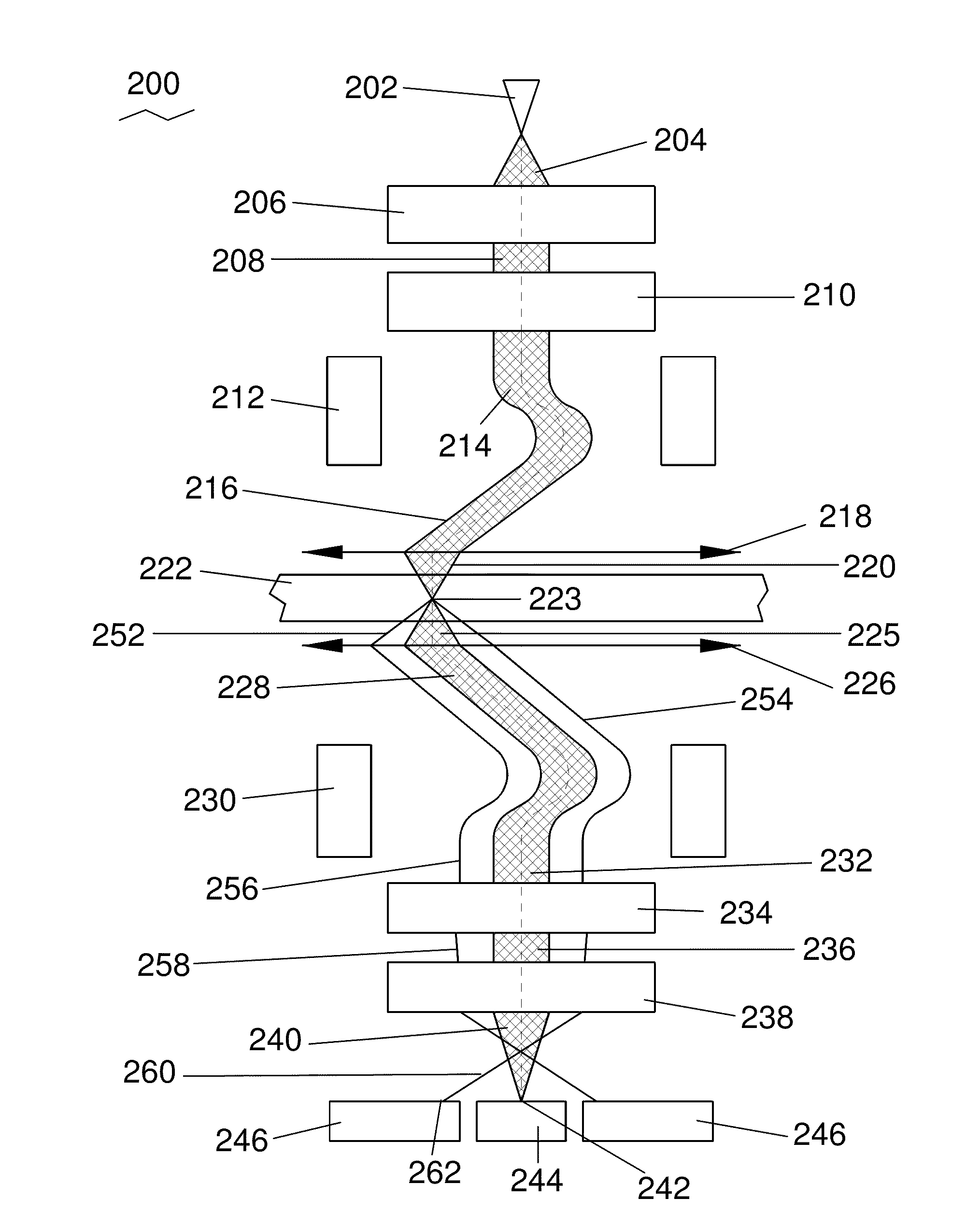
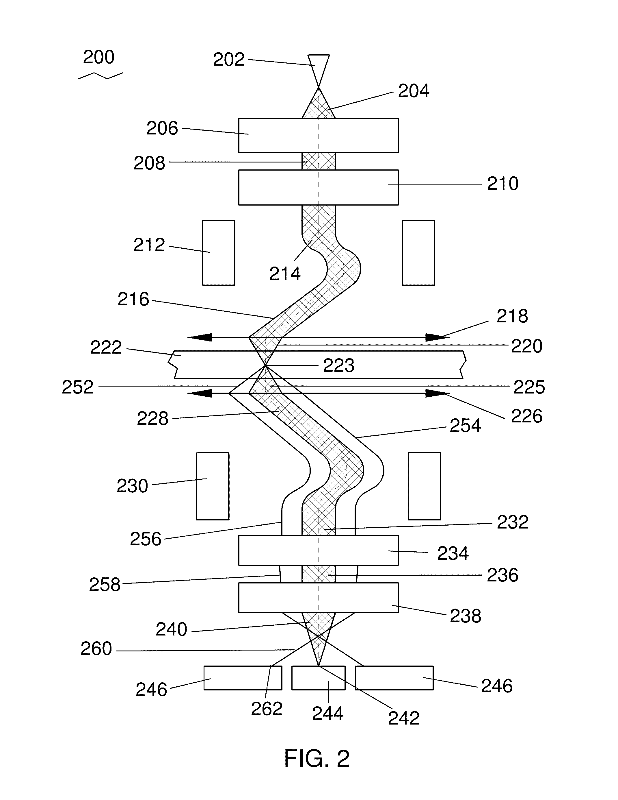
[0022]Applicants have found that the use of a corrector below the sample enhances contrast. Embodiments of the invention will enable a new application that can provide 3D information about the specimen. Moreover, due to the capability of the Real Bright Field (RBF) detector to remove inelastic scattered electrons, the technique can be used to image thick specimens.

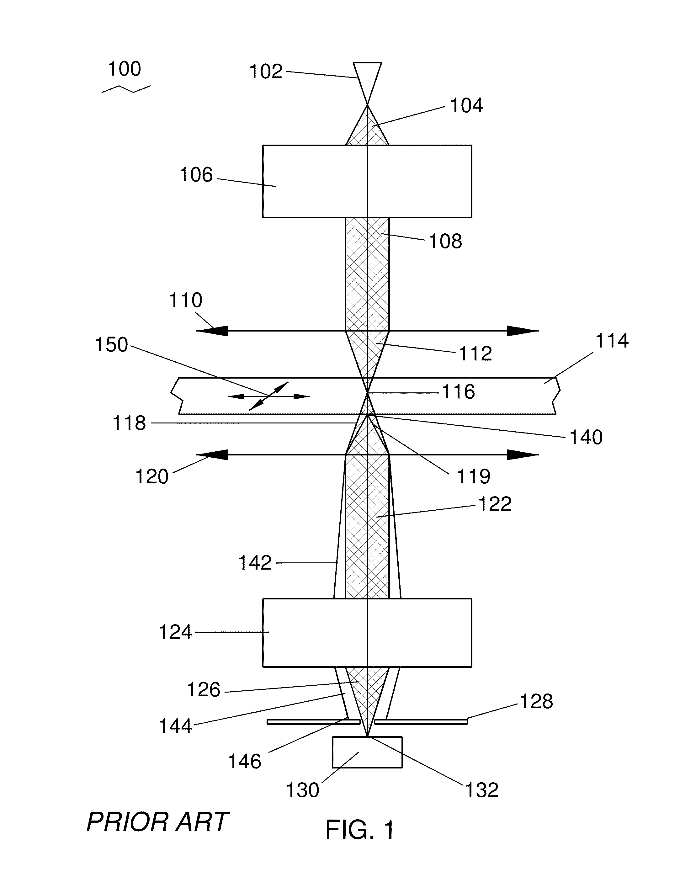
[0023]Traditionally, STEM detection was performed in or near the back focal plane, also known as the diffraction plane, of the lens below the sample. The detector in confocal microscopy was positioned in the real image plane of the lens below the sample, and was used primary for three-dimensional imaging because of ...


PUM


Abstract

A scanning confocal transmission electron microscope includes a descan deflector and a corrector below the sample. The microscope uses a detector that is preferably significantly larger than the resolution of the microscope and is positioned in the real image plane, which provides improved contrast, particularly for light elements.

Description

[0001]The present application claims priority from U.S. Prov. Pat. App. No. 61 / 364,355, filed Jul. 14, 2010, which is hereby incorporated by reference.TECHNICAL FIELD OF THE INVENTION[0002]The present invention relates generally to transmission electron microscopy and in particular to improving contrast in a scanning confocal electron microscope.BACKGROUND OF THE INVENTION[0003]In confocal microscopy, an illumination source is focused onto a point at the sample, and then an image of the sample point is formed at an aperture.[0004]The focal point of the illumination source is scanned across the sample, and the light intensity at the aperture is used to form an image, with the intensity of each image point corresponding to the intensity of light passing through the aperture. By focusing the illumination source at different depths within a sample, images from different depths in the interior of a transparent sample can be formed because the small aperture blocks electrons scattered fro...

Claims


Application Information

Patent Timeline
IPC IPC(8): G01N23/04
CPCH01J37/28H01J2237/24465H01J37/244H01J2237/1534H01J2237/2802H01J2237/24485
Inventor LAZAR, SORINFREITAG, BERT HENNINGTIEMEIJER, PETER CHRISTIAAN
Owner FEI CO
Why Eureka
Try Eureka