Corner cube enhanced photocathode

Active Publication Date: 2012-01-19
BAE SYST INFORMATION & ELECTRONICS SYST INTERGRATION INC
View PDF13 Cites 40 Cited by
  • Summary
  • Abstract
  • Description
  • Claims
  • Application Information

AI Technical Summary

Benefits of technology

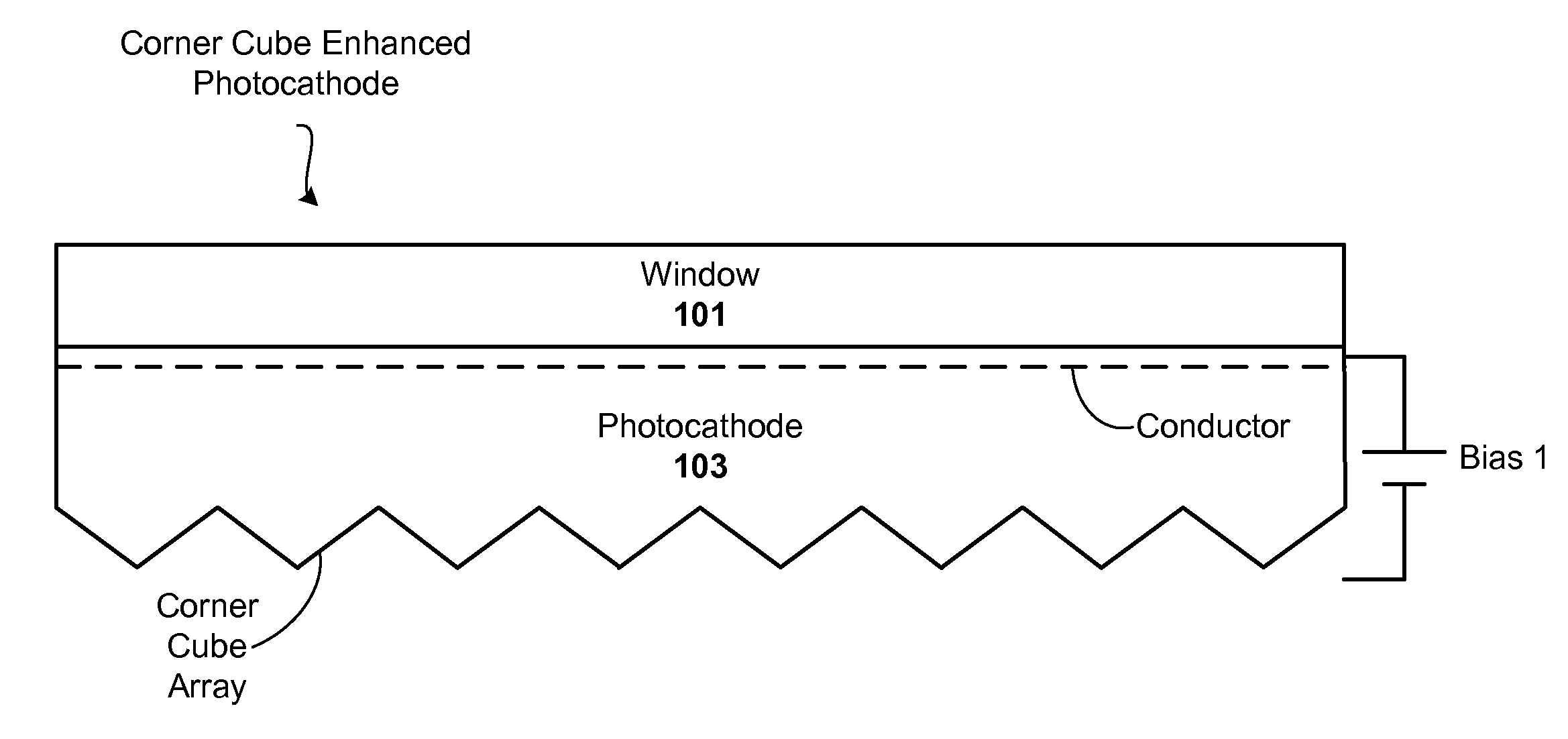
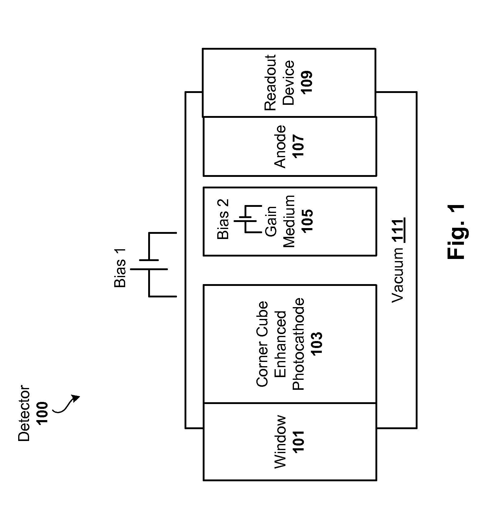
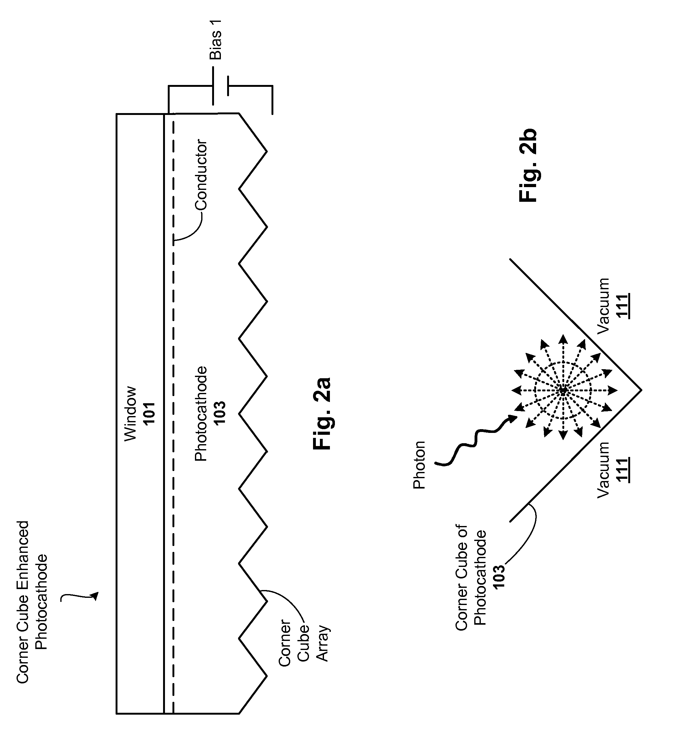
[0005]One embodiment of the present invention provides a photocathode device. The device includes a window (transparent to spectrum range of interest), and a photocathode layer. The photocathode layer has an input surface optically coupled to the window and a vacuum-side surface having a corner cube array formed therein. The corner cube array is made of the same material as the photocathode layer. The device may further include a gain medium operatively coupled to the vacuum-side surface via a vacuum and bias, and an anode operatively coupled to the gain medium by the vacuum. In one such c

Problems solved by technology

Photo-emissive devices generally have limited quant

Method used


Image

  • Corner cube enhanced photocathode
  • Corner cube enhanced photocathode
  • Corner cube enhanced photocathode

Examples


Embodiment Construction

[0015]Techniques are disclosed for improving the quantum efficiency of photocathode devices. The techniques allow for an increase in the optical thickness of the photocathode device, while simultaneously allowing for an increase in the probability of electron escape into the vacuum of the device. The techniques are particularly useful in detector and imaging systems that operate in the ultra-violet (UV), visible, and infrared (IR) light spectrums, such as those implemented as low light level systems.

[0016]General Overview

[0017]As previously explained, conventional photo-emissive devices have limited quantum efficiency. One reason for this limited quantum efficiency is due to conflicting design requirements. In particular, for a high probability of photoelectron generation, the photocathode should be optically thick. On the other hand, for a high probability that a photoelectron will escape into the vacuum of the detector, the photocathode should be physically thin.

[0018]In standard ...


PUM


Abstract

Techniques are disclosed for improving the quantum efficiency of photocathode devices. The techniques allow for an increase in the optical thickness of the photocathode device, while simultaneously allowing for an increase in the probability of electron escape into the vacuum of the device. The techniques are particularly useful in detector and imaging. In one embodiment, a photocathode device is provided that has an array of corner cubes fabricated in a surface of the photocathode. The corner cube array is made of the same material as the photocathode layer. The device may be, for example, a detector or image intensifier that operates in the UV, visible, and IR light spectrums, and may further include a gain medium, anode, and readout device. Techniques for forming the device are also provided.

Description

RELATED APPLICATIONS[0001]This application is a National Stage of International Application No. PCT / US10 / 21485, filed Jan. 20, 2010, which claims priority to U.S. Provisional Application No. 61 / 146,501, filed Jan. 22, 2009. Each of these applications is herein incorporated by reference in its entirety.FIELD OF THE INVENTION[0002]The invention relates to photo-emissive devices, and more particularly, to techniques for improving the quantum efficiency of such devices.BACKGROUND OF THE INVENTION[0003]As is known, a photocathode is a negatively charged electrode in a light detection device, such as a phototube or photomultiplier. The electrode is coated with a photosensitive material, such that when light impinges on the photosensitive material, the absorbed energy causes electron emission due to the photoelectric effect. Current photocathode designs are typically planar and have not structurally changed since the early phototubes.[0004]Photo-emissive devices generally have limited quan...

Claims


Application Information

Patent Timeline
IPC IPC(8): H01L31/0264H01L31/0336
CPCG02B5/122H01J9/12G01J1/44
Inventor DEFLUMERE, MICHAEL E.SCHOECK, PAUL W.
Owner BAE SYST INFORMATION & ELECTRONICS SYST INTERGRATION INC
Why Eureka
Try Eureka