
Time-Based Trace Facility

a trace facility and time-based technology, applied in the field of software monitoring and tracing, can solve the problems of inability of users to articulate their needs, inability to achieve the effect of product development, and inability to meet user needs

Inactive Publication Date: 2012-01-19
IBM CORP
View PDF10 Cites 36 Cited by
  • Summary
  • Abstract
  • Description
  • Claims
  • Application Information

AI Technical Summary

Benefits of technology

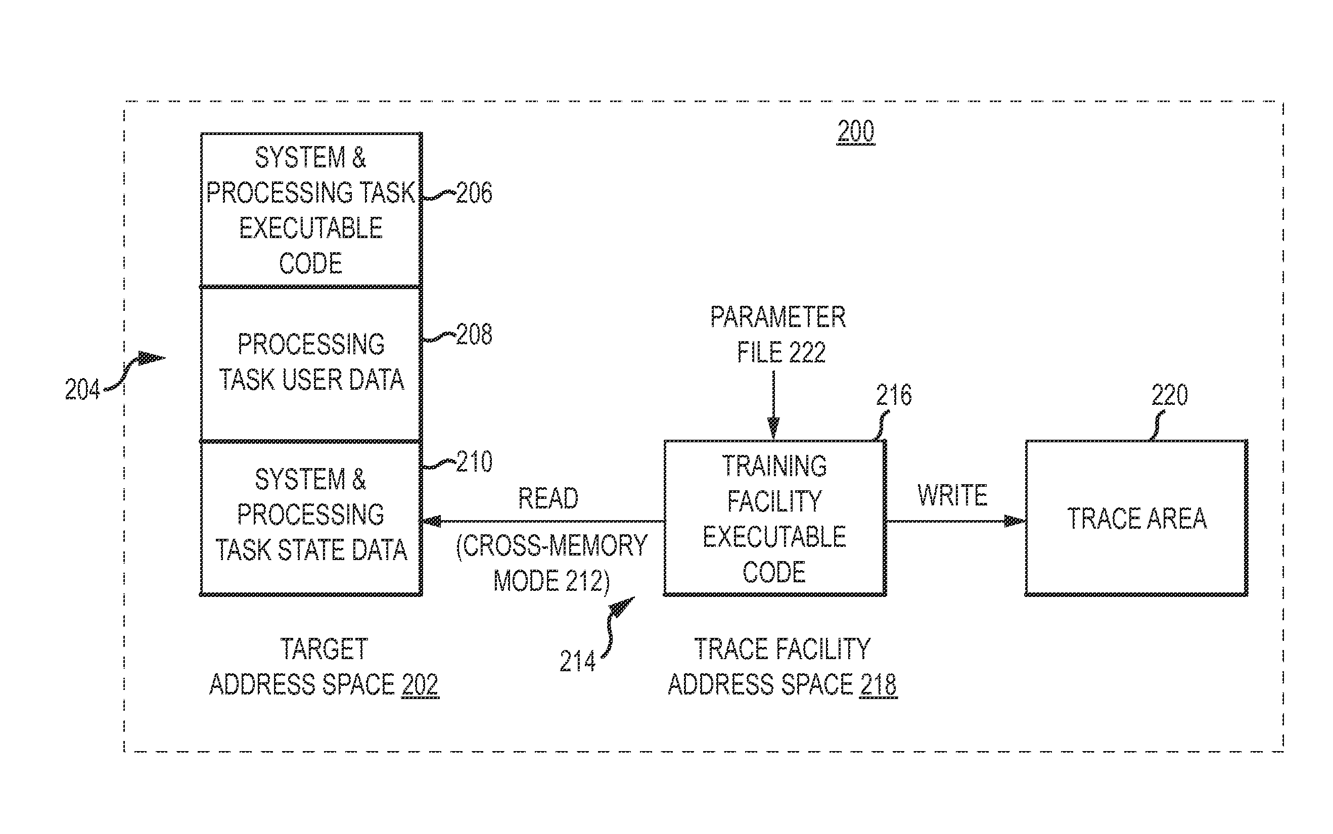
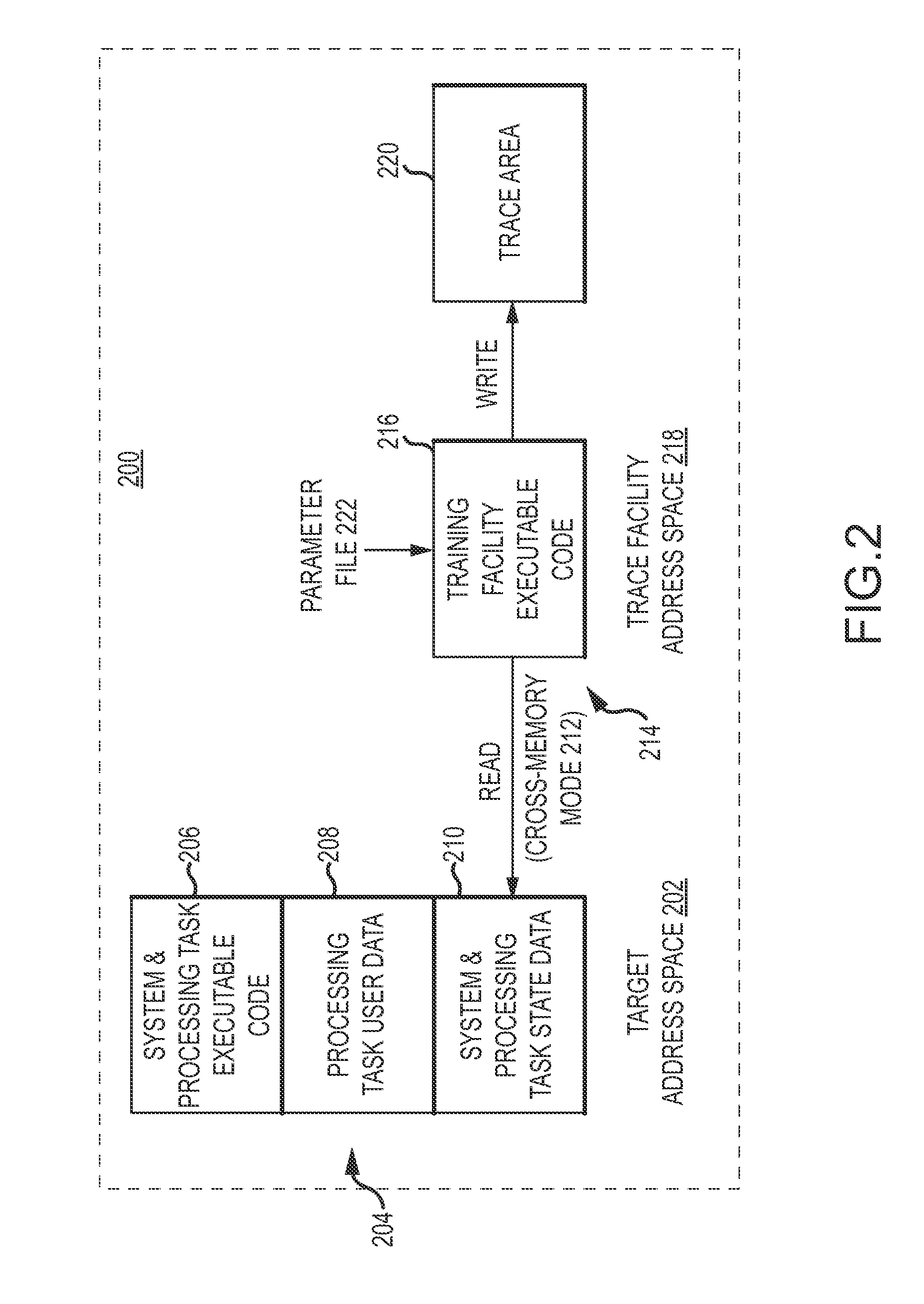
[0012]According to one embodiment of the present invention, in a computer system in which the OS (such as IBM's z / OS) and one or more CPUs support one or more cross-memory modes a time-based trace facility implemented in a trace address space reads state data from a different target address space for a processing task according to a time-based schedule and writes the state data to a trace area. The schedule may specify a finite time interval or may specify continuous read out. The trace area may be located in the target or trace address spaces, a data space, or in external storage. The one or more CPUs allocate a time slice of CPU resources to the target address space to run the processing task executable code to update the state data and allocate a different time slice of CPU resources to the trace address space to run the trace facility executable code to read state data from the target address space using the cross-memory mode. Because the trace facility resides in a different address space, the executable code does not interfere with run-time behavior, performance or resource usage of the processing task. This approach allows a large amount of state data to be saved frequently to enable problem determination without interfering with the operation of the processing task.

Problems solved by technology

Users of computing applications often encounter various sorts of problems and inconsistencies while using the applications.
Understanding what is important to users of a particular software application product is a challenge for software application developers.
Some problems inherent in these methods, however, include the inability of users to articulate their needs, the artificiality of surveys produces feedback that is not meaningful, and users of forums are typically technical fans of the product so that the results may be of little practical use to the product developers.
The problem is to provide a meaningful solution for gathering real user feedback in real time on a regular basis, and providing this data back to the program developer where it can be analyzed and used in enhancing and improving the application.
It has been found that this “compile-time” method of instrumentation is not really effective for a number of reasons.
At the particular code level, it is difficult to be judicious in selecting code points for instrumentation.
A large number of instrumentation points can negatively affect the application's performance.
In some instances, the data can be large and therefore cumbersome to analyze, and at other times, it may be sparse and therefore of very little practical use.

Method used


Image

  • Time-Based Trace Facility
  • Time-Based Trace Facility
  • Time-Based Trace Facility

Examples


Embodiment Construction

[0029]It will be readily understood that the components of the present invention, as generally described and illustrated in the Figures herein, could be arranged and designed in a wide variety of different configurations. Thus, the following more detailed description of the embodiments of the invention, as represented in the Figures, is not intended to limit the scope of the invention, as claimed, but is merely representative of certain examples of presently contemplated embodiments in accordance with the invention. The presently described embodiments will be best understood by reference to the drawings, wherein like parts are designated by like numerals throughout.

[0030]There are many reasons to trace a running application, process, job or other software task, referred to throughout generically as “processing tasks”. To name a few: (1) to understand the task's run-time behavior including the occurrence of any errors; (2) to ensure that the task achieves an expected performance; and...


PUM


Abstract

Method, system, and computer program product embodiments of a time-based trace facility for facilitating software debugging without interfering with the run-time behavior, performance or resource usage of the traced software are provided. The trace facility resides in a different address space than the target address space and uses different time-slices of CPU resources to execute the instructions in the address spaces. The trace facility uses a cross-memory mode to read the state data from the target address space in accordance with a time schedule. The trace facility writes the state data to a trace area, which may be located in either the target or trace address spaces or external storage. With this approach, the trace facility can read a large amount of state data frequently to construct the type of historical record needed to analysis run-time behavior, performance and resource usage. The trace facility may use a parameter file to configure a particular trace e.g. specify the target address space, one or more processing tasks within the target address space, a specific trace module, filters to extract specific state data, the time interval, the trace area, etc.

Description

BACKGROUND[0001]1. Field of the Invention[0002]The present invention relates to the field of software monitoring and tracing, and more specifically, to a time-based trace facility for recording state data to build an historical record for software in a computer environment.[0003]2. Description of the Related Art[0004]Users of computing applications often encounter various sorts of problems and inconsistencies while using the applications. Designing computer software that will minimize user problems requires knowledge as to how the user is making use of the application and the tasks that are trying to be accomplished by use of the applications. The design process typically includes iterative design and user testing of those designs in order to identify where users have problems so that design flaws can be accurately addressed and fixed. A thorough knowledge of problems that users encounter in existing products is also critical if design mistakes are to be avoided for future versions ...

Claims


Application Information

Patent Timeline
Patent Type & Authority Applications(United States)
IPC IPC(8): G06F11/32
CPCG06F11/3636G06F11/3466
Inventor MASSER, JOEL L.REED, DAVID C.SMITH, MAX D.
Owner IBM CORP
Learn More