
Wear-resistant separating device for removing sand and rock particles

a technology of separating device and rock particles, which is applied in the direction of drinking water installation, borehole/well accessories, construction, etc., can solve the problems of filter damage, low wear resistance, and wire meshes, and achieves the effects of reducing the tendency to fracture, improving wear resistance, and prolonging service li

Active Publication Date: 2012-01-26
3M INNOVATIVE PROPERTIES CO +1
View PDF19 Cites 21 Cited by
  • Summary
  • Abstract
  • Description
  • Claims
  • Application Information

AI Technical Summary

Benefits of technology

The invention is a separating device for removing sand and rock particles from liquids or gases extracted from deep wells. It consists of a ceramic filter module with an annular stack of brittle-hard discs, which are axially braced and have a defined separating gap for removing sand and rock particles. The device is more resistant to abrasion and corrosion than conventional sand filters, has a longer service life, and allows for higher extraction rates. It does not require additional mechanical support and does not change its stability over time. The ceramic sand filter modules are of a single-ply configuration and are not influenced by multi-ply fabric arrangements, which increase flow resistance and tend to become clogged. The device ensures the removal of particles in direct oncoming and passing-through flow, without energy dissipation or deflection.

Problems solved by technology

A major disadvantage of these constructions with metal woven wire meshes, wire grids or wire windings is their low resistance to wear.
On account of the abrasive or erosive effect of the sand and rock particles flowing in at a high flow velocity, the filters are destroyed and the extraction pipes are damaged.
At the same time, the productivity of the extraction decreases, since the sand is no longer effectively filtered out but is transported further with the extraction medium.
A further problem is the corrosive wear occurring on the filters and extraction pipes as a result of the use of treatment fluids.
This corrosive wear in turn exacerbates the abrasive wear.
One problem of the solutions described in these two documents is that, on account of their low fracture toughnesses, filters of porous ceramic materials tend to fracture as a result of flexural loading.
The ultimate bending strength is generally well below 30% of that of the corresponding solid material and is therefore not sufficient for the mechanical loads under the operating conditions in wells drilled in rock.
A further problem is that the abrasion resistance of porous ceramic materials is much less than that of solid ceramic materials.
A disadvantage of this solution is that the improved wear protection is accompanied by an energy dissipation of the flowing medium; the outer sleeve does not act as a filter but as a flow resistance, which worsens the output.
This solution cannot be realized from ceramics.
The central lead-throughs for the threaded rods would weaken ceramic elements and reduce the load-bearing capacity.
The spacers are of a flat form; they do not allow compensation for flexural stresses.
Further disadvantages of the screen filter described in U.S. Pat. No. 5,249,626 of glass-reinforced polypropylene are its insufficient erosion / abrasion resistance and insufficient corrosion resistance.
However, in the case of ceramic, the rigid configuration with the fixedly connected flat-form spacers would have the effect that tensile and flexural stresses occurring could not be absorbed, which would lead to a considerable risk of fracture and possible complete destruction of the sand filter.
Moreover, the production of such a construction from ceramic would be very complex.

Method used


Image

  • Wear-resistant separating device for removing sand and rock particles
  • Wear-resistant separating device for removing sand and rock particles
  • Wear-resistant separating device for removing sand and rock particles

Examples


example 1

Resistance to Erosion

[0173]To determine the erosive wear, plates (about 75×75×50 mm) of steel, a porous, sintered silicon carbide ceramic and fine-grained, densely sintered silicon carbide ceramic (SSiC) of the type EKasic® F (ESK Ceramics GmbH & Co. KG) were subjected to a sand blasting test. The steel specimen served in this case as a reference.

[0174]The tests were carried out by means of a sand blasting installation. Four different supporting materials that are typically used in offshore drilling operations served as blasting media: (1) 100 Mesh Frac Sand, (2) 16 / 20 Mesh Frac Sand, (3) 20 / 40 Mesh Frac Sand and (4) 20 / 40 Mesh Frac Sand High Strength. The blasting pressure was 2 bar and the blasting duration 2 hours, the jet being applied almost in the form of a point at an angle of 90° to the surface. The depth and width of the blasting impression characterize the erosive wear (see Table 1).

[0175]The tests show that the densely sintered silicon carbide ceramic is much more resista...


PUM


Abstract

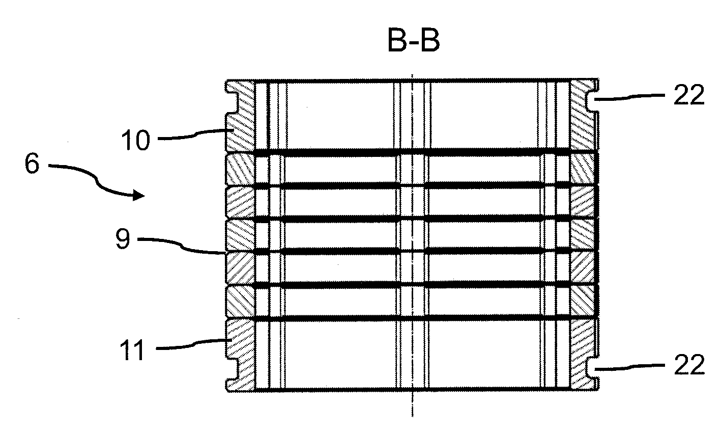
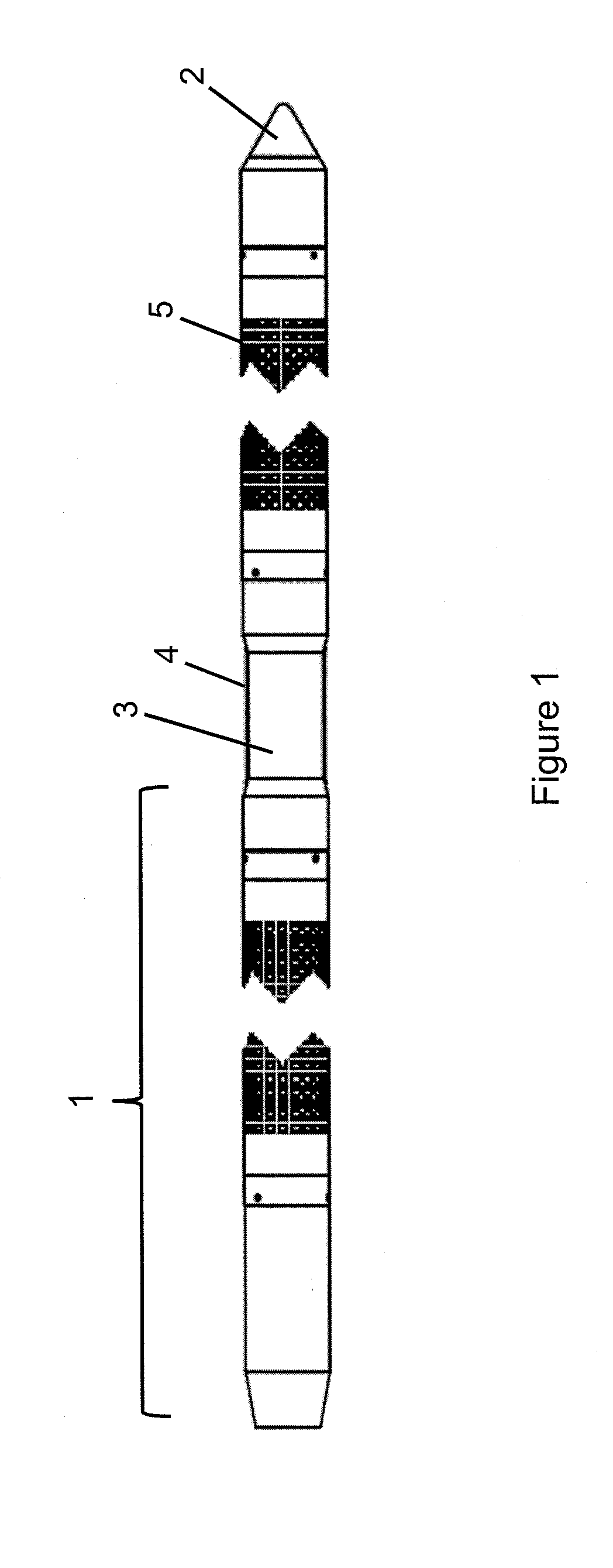
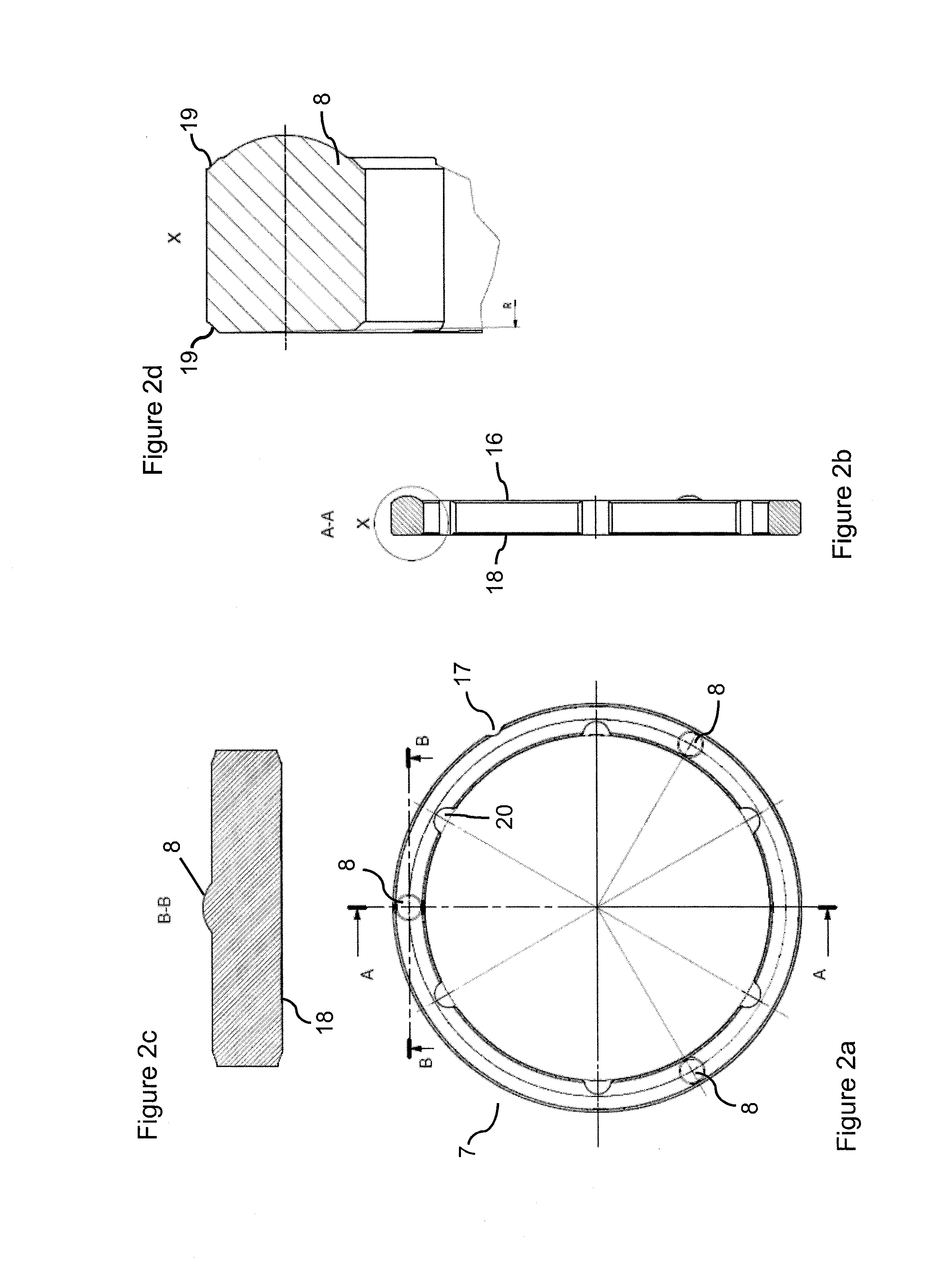
The subject matter of the invention is a separating device for removing sand and rock particles which is suitable as an integral component part of extraction equipment for the extraction of liquids or gases from deep wells, the separating device comprising at least one ceramic filter module (1), the filter module (1) comprisinga) an annular stack (6) of brittle-hard annular discs (7), the upper side (16) of which has at least three elevations (8) uniformly distributed over the circular circumference of the discs, the discs (7) being stacked and braced in such a way that a separating gap (9) for the removal of sand and rock particles is present in each case between the individual discs (7),b) a coupling-on element (10) at the upper end and a coupling-on element (11) at the lower end of the annular stack (6),c) a clamping device (14, 15) for the axial bracing of the annular stack (6),d) an outer cage (5) for the mechanical protection of the filter module (1),e) a coupling element (12) at the upper end and a coupling element (13) at the lower end of the filter module (1) for connecting the filter module (1) to further components of the extraction equipment.The subject matter of the invention likewise covers the use of a separating device according to the invention for removing sand and rock particles in a process for extracting liquids or gases from wells drilled in rock or deep wells.

Description

FIELD OF THE INVENTION[0001]The invention relates to a novel separating device with improved erosion and abrasion resistance, which is suitable as an integral component part of extraction equipment for use in the extraction of oil, water and gas mixtures or the individual components thereof from deep wells, with the aid of which solids such as sand and rock particles can be removed from the liquids and gases to be extracted. The separating device serves in particular for preventing the corrosive and abrasive wearing of the extraction equipment by sand and rock particles. At the same time, the separating device is corrosion-resistant with respect to treatment fluids.BACKGROUND OF THE INVENTION[0002]In the extraction of liquids and gases, such as mineral oil and natural gas, from deep wells, there is often the problem that influxes of sand from the oil and gas deposits make extraction more difficult. This is the case in particular whenever hydrocarbon production takes place from uncon...

Claims


Application Information

Patent Timeline
Patent Type & Authority Applications(United States)
IPC IPC(8): E21B43/08
CPCE21B43/088E21B43/086E21B43/082
Inventor WILDHACK, STEFANIEKAYSER, ARMINJOLY, SAMUELMUSSIG, SIEGFRIEDWAHRMANN, KLAUSPOHLING, FABIAN
Owner 3M INNOVATIVE PROPERTIES CO
Learn More