Electromechanical vehicle brake

a technology brakes, applied in the field of electronic mechanical brakes, can solve the problems of limited mobility of rolling elements and difficult production, and achieve the effect of simplifying the production of ball screws

Active Publication Date: 2012-01-26
CONTINENTAL TEVES AG & CO OHG
View PDF6 Cites 46 Cited by
  • Summary
  • Abstract
  • Description
  • Claims
  • Application Information

AI Technical Summary

Benefits of technology

[0006]This invention relates to simplifying the production of a ball screw which is equally suitable for use in combined brakes and for use in brakes with purely electromechanical actuation.

Problems solved by technology

In this case the rolling elements have limited mobility between two stops rigidly connected to the threaded nut.
A disadvantage of this arrangement is that the stops are inserted into the threaded nut from outside, as pins through a bore.
Because the bore must meet the thread convolution precisely when drilling into the threaded nut from outside, production is difficult.

Method used


Image

  • Electromechanical vehicle brake
  • Electromechanical vehicle brake
  • Electromechanical vehicle brake

Examples


Embodiment Construction

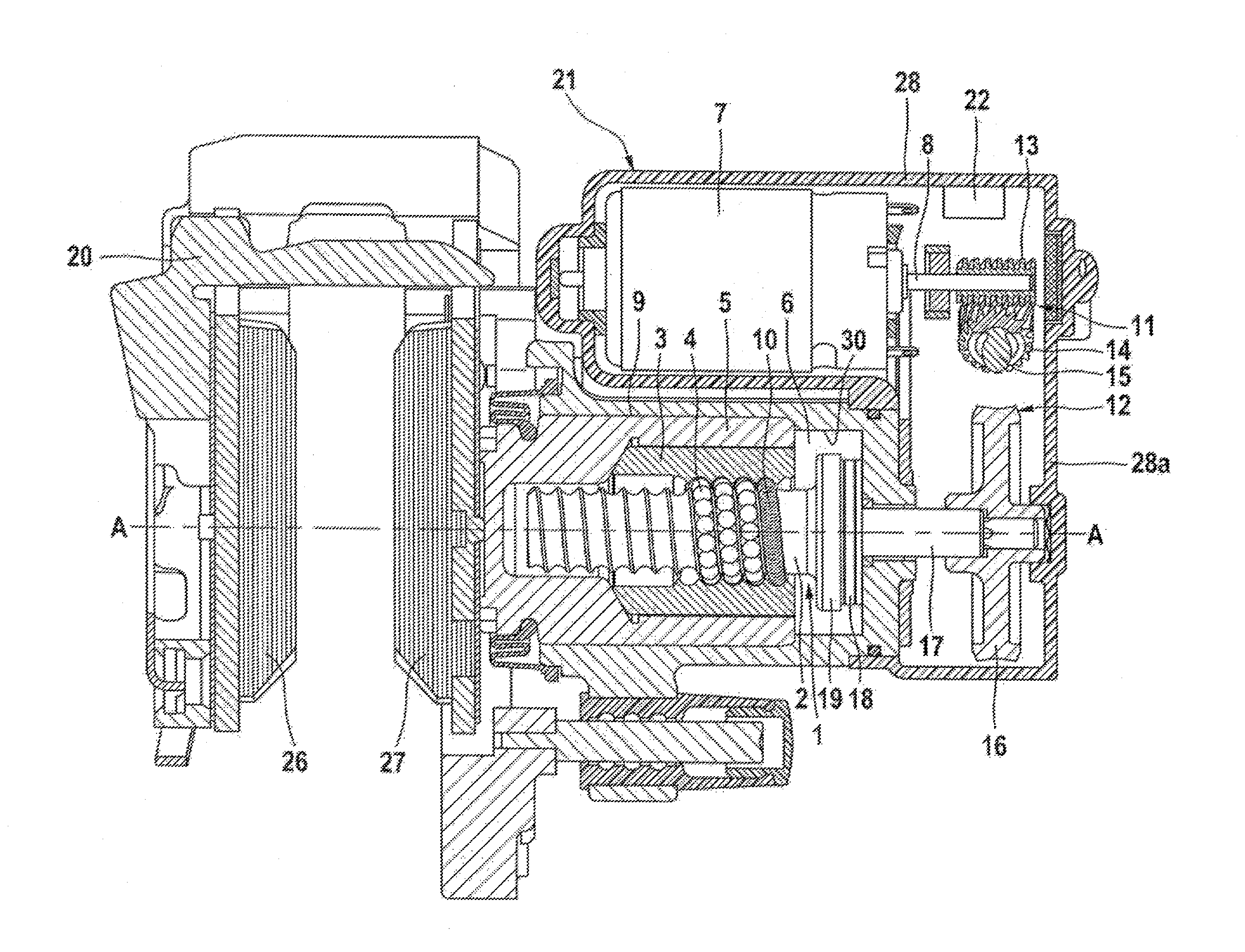
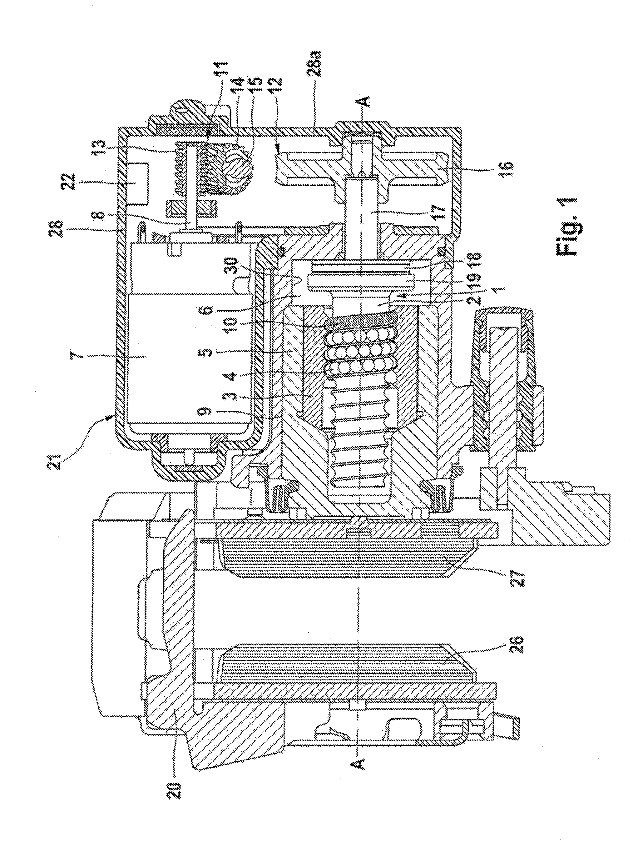
[0015]The hydraulic vehicle brake represented in FIG. 1 comprises, on the one hand, a hydraulically actuatable service brake and, on the other, an electromechanically actuatable parking brake. In the example shown, the vehicle brake is in the form of a floating-caliper disk brake, the functioning of which, produced by hydraulic actuation, is well-known to the person skilled in the art, and for that reason does not need to be explained in more detail. An electromechanical actuator 7 or an electric motor 7, which is integrated in a drive module 21 together with a two-stage transmission, the necessary sensors and an electronic control unit 22, is used to actuate the parking brake. The abovementioned vehicle brake further comprises a brake housing or a brake caliper 20 which extends around the outer edge of a brake disk (not shown), and two brake pads 26, 27 arranged on each side of the brake disk. The brake housing 20 forms on its inner side a brake cylinder 9 which receives an axially...


PUM


Abstract

A combined electromechanical vehicle brake has a hydraulically activated operating brake and an electromechanically activated parking brake apparatus. A hydraulic operating pressure chamber in a brake housing is delimited by a brake piston that can be loaded by hydraulic pressure to carry out operating braking actions. The brake piston can be activated along a longitudinal piston axis to achieve a braking effect. The parking brake apparatus acts upon the brake piston by a gear unit because the gear unit converts the rotational movement of an electromechanical actuator into a translational movement, causing the brake piston to be activated to carry out parking brake processes and remain in the activated position. The gear unit has a threaded spindle and a threaded nut that contact one another via a plurality of rolling elements. A spring element allows the rolling elements to slip when the gear unit is activated in the unloaded state.

Description

CROSS REFERENCE TO RELATED APPLICATIONS[0001]This application is the U.S. National Phase Application of PCT / EP2010 / 053434, filed Mar. 17, 2010, which claims priority to German Patent Application No. 10 2009 015 514.7, filed Apr. 2, 2009, and German Patent Application No. 10 2009 019 793.1, filed May 2, 2009, the contents of such applications being incorporated by reference herein.FIELD OF THE INVENTION[0002]The present invention relates to an electromechanical, in particular combined, vehicle brake comprising a hydraulically actuatable service brake and an electromechanically actuatable parking brake device, wherein a hydraulic operating pressure chamber is delimited in a brake housing by a brake piston which can be loaded by hydraulic pressure medium in order to perform service braking operations, such that the brake piston can be actuated along a longitudinal piston axis in order to produce a braking effect, and wherein the parking brake device acts on the brake piston by means of...

Claims


Application Information

Patent Timeline
Patent Type & Authority Applications(United States)
IPC IPC(8): B60T7/00B60T13/58F16D65/18
CPCF16D65/18F16D2121/02F16D2121/24F16D2123/00Y10T74/19749F16D2125/52F16H25/2233Y10T74/18576F16D2125/40
Inventor WINKLER, THOMAS
Owner CONTINENTAL TEVES AG & CO OHG
Why Eureka
Try Eureka