Integrated energy absorber and air flow management structure

a technology of energy absorber and air flow management, which is applied in the direction of roofs, bumpers, vehicular safety arrangments, etc., can solve the problems of limited ability to deal with various engine conditions, no known system is adapted to work, and additional concerns, so as to achieve the effect of minimizing air leakag

Active Publication Date: 2012-01-26
SHAPE CORP
View PDF42 Cites 146 Cited by
  • Summary
  • Abstract
  • Description
  • Claims
  • Application Information

AI Technical Summary

Benefits of technology

[0009]In another aspect of the present invention, an assembly for a vehicle includes a power plant. The assembly comprises a shutter assembly positioned to control air flow toward the engine, and including shutter vane members movable to different air flow positions to selectively control air flow through the shutter section, at least one of the shutter vane members having a cross section with two spaced arms a

Problems solved by technology

Baffles and air dams are often used, but they usually are fixed and hence limited in their ability to deal with various engine conditions (such as engine temperature at engine start up and continuing operation) and various environmental conditions (such as high or low outside temperatures).
However, as best understood, none of the known systems are adapted to work upon failure of its opening mechanism or upon decoupling of shutters from the respective opening mechanism.
There are also additional concerns outside of air control.
For example, there is limited space in front of a vehicle engine and around a vehicle's bumper system, and the presence of any air flow control mechanism and control structure can requir

Method used


Image

  • Integrated energy absorber and air flow management structure
  • Integrated energy absorber and air flow management structure
  • Integrated energy absorber and air flow management structure

Examples


Embodiment Construction

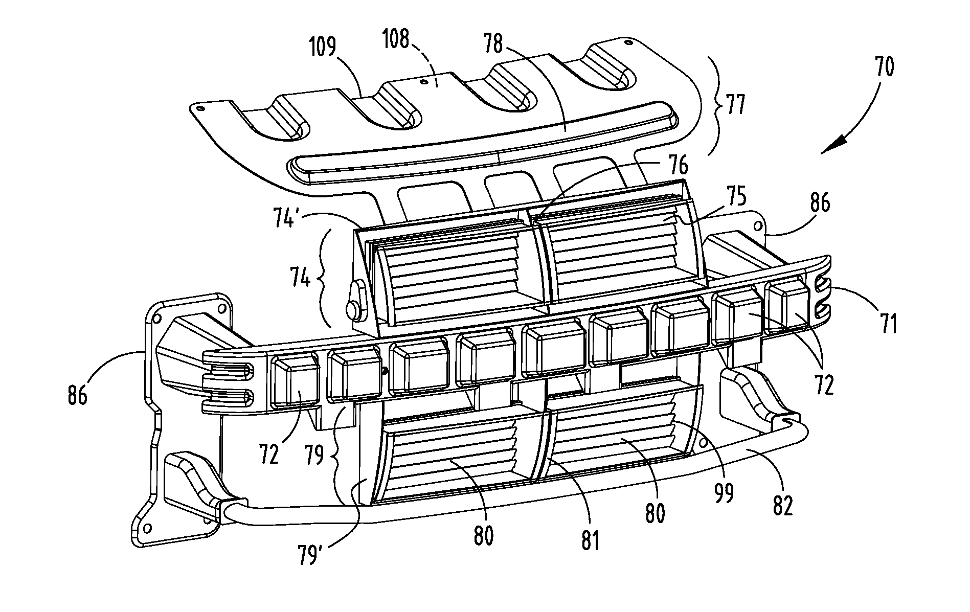
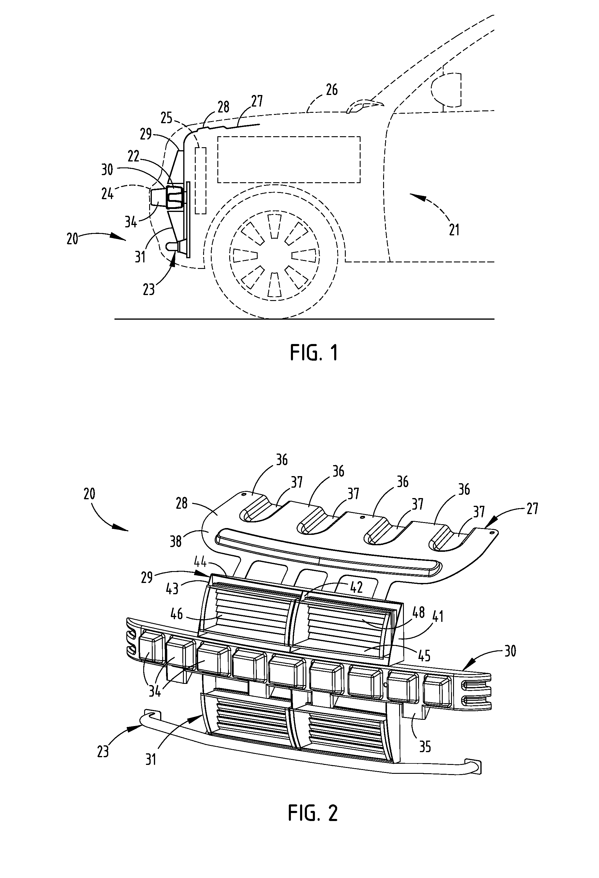
[0023]The present integrated assembly 20 (FIGS. 1-2) is configured for assembly to a vehicle 21 having a bumper reinforcement beam 22, a pedestrian impact bar 23, a fascia 24, a radiator 25, and a hood 26. The integrated assembly 20 includes an upper fascia support section 27, an upper leg energy absorber section 28, an upper air shutter section 29, a bumper energy absorber / lower fascia support section 30, and a lower air shutter section 31. A polymeric lower leg energy absorber section can be positioned on a front of the pedestrian impact bar 23 if desired. Upon assembly, the bumper energy absorber section 30 is position on a face of the bumper reinforcement beam 22.

[0024]The bumper energy absorber section 30 mates against a front of the beam 22 and includes crush lobes 34 configured to absorb substantial energy upon impact against an object according to a desired force / deflection curve. The bumper energy absorber section 30 also includes multiple triangular-shaped downward-extendi...


PUM


Abstract

An integrated assembly includes a bumper energy absorber section with crush lobes for abutting a bumper beam, an upper air shutter section with subassembled shutter members movable between closed and open positions, a first actuator mechanism for moving the shutter members between positions, an upper fascia support section with upper leg crush lobe therein above the upper air shutter section, a lower air shutter section with subassembled lower shutter members movable between closed and open positions, a second actuator mechanism for moving the lower shutter members between the positions; and a lower leg energy absorber section attached below the lower air shutter section and configured to abut (or replace) a face of a secondary pedestrian impact bar. The shutter members may be molded to a shutter frame using over molding technology rather than separately, manually assembled.

Description

[0001]This application claims benefit under 35 USC §119(e) of provisional application Serial No. 61 / 366,325, filed Jul. 21, 2010, entitled INTEGRATED ENERGY ABSORBER AND AIR FLOW MANAGEMENT STRUCTURE, the entire contents of which are incorporated herein by reference.BACKGROUND[0002]The present invention relates to vehicle front end components for energy absorption and air flow, and more particularly relates to an energy absorber with integrated air flow management structure incorporated therein, such as shutters and a shutter control mechanism.[0003]In modern passenger vehicles, control of air flow in and around the vehicle's engine is important to engine performance and overall operation. Baffles and air dams are often used, but they usually are fixed and hence limited in their ability to deal with various engine conditions (such as engine temperature at engine start up and continuing operation) and various environmental conditions (such as high or low outside temperatures). Some a...

Claims


Application Information

Patent Timeline
IPC IPC(8): B62D25/08B60R19/26
CPCB60K11/085B60R19/12B60R19/18B62D35/005B60R2019/486B62D25/084B60R2019/1873Y02T10/88
Inventor EVANS, DARINRALSTON, DANZABIK, BENJAMIN R.
Owner SHAPE CORP
Why Eureka
Try Eureka