Bidirectional polyphase multimode converter including boost and buck-boost modes

a polyphase, multi-mode technology, applied in the direction of electric vehicles, transportation and packaging, secondary cell servicing/maintenance, etc., can solve the problems of damage to the converter and/or the energy storage system, and achieve the effect of high energy, efficient and safe handling conditions

Active Publication Date: 2012-01-26
TESLA INC
View PDF11 Cites 34 Cited by
  • Summary
  • Abstract
  • Description
  • Claims
  • Application Information

AI Technical Summary

Benefits of technology

[0008]Disclosed is a charging system and method that is capable of providing high energy to a high performance energy storage system for charging the energy storage system while efficiently and safely handling conditions of a too “high” line-in voltage relative to a voltage level of the energy storage system. The charging system using a multiphase line voltage for charging an energy storage system (ESS) using a polyphase motor drive circuit communicated to a polyphase motor, the polyphase motor drive circuit including a plurality M of driver stages, one driver stage for each phase of the polyphase motor with each driver stage coupled across the energy storage system, the system including: a converter, coupled to the energy storage system and to the plurality of driver stages, having a boost mode and a boost-buck mode, the converter converting the multiphase line voltage to a first charging voltage using a first set of N number of the plurality of driver stages when in the boost mode, with N less than M, wherein the first charging voltage is communicated to the energy storage system and wherein the first charging voltage is greater than the multiphase line voltage, and the converter converting the multiphase line voltage to a second charging voltage using a second set of P number of the plurality of driver stages when in the boost-buck mode, with P greater than N, wherein the second charging voltage is communicated to the energy storage system and wherein the second charging voltage is less than the multiphase line voltage; a mode control, responsive to a voltage comparison between the multiphase line voltage and an ESS voltage of the energy storage system, for changing the converter from the boost mode to the boost-buck mode when the multiphase line voltage has a first predetermined relationship to the ESS voltage and for changing the converter from the boost-buck mode to the boost mode when the multiphase line voltage has a second predetermined relationship to the ESS voltage; and a controller, coupled to the converter and to the mode control, for operating the converter and the mode control to charge the energy storage system in the boost mode and in the boost-buck mode.

Problems solved by technology

(Depending upon circuit topology, one reason the voltage converter cannot charge battery assembly is because the described relative voltages results in uncontrollable current flow out of the converter, potentially seriously damaging the converter and / or the energy storage system.)
This is undesirable to say the least, particularly given the consequences of damage and costs of the components in an electric vehicle or other high-energy system.
Solutions for electric vehicles must often meet tight budgets for space, weight, and component costs.

Method used


Image

  • Bidirectional polyphase multimode converter including boost and buck-boost modes
  • Bidirectional polyphase multimode converter including boost and buck-boost modes
  • Bidirectional polyphase multimode converter including boost and buck-boost modes

Examples


Embodiment Construction

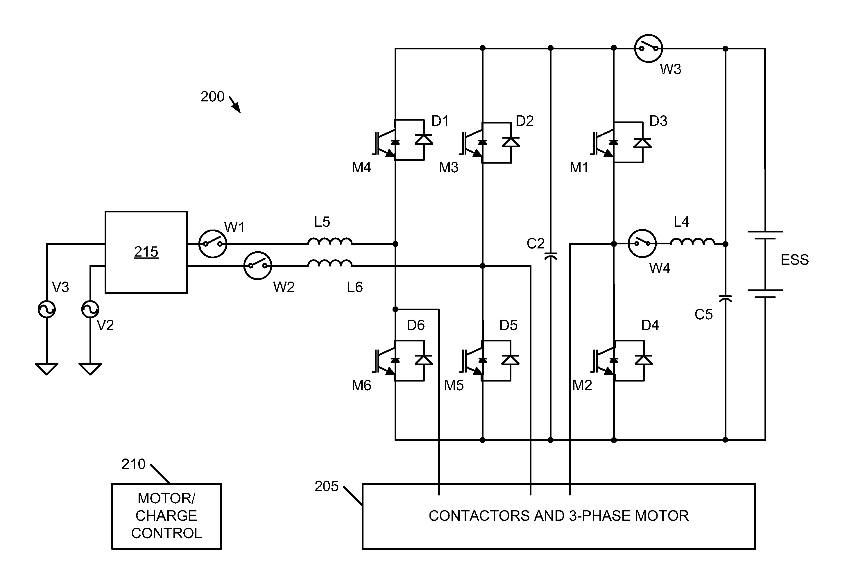
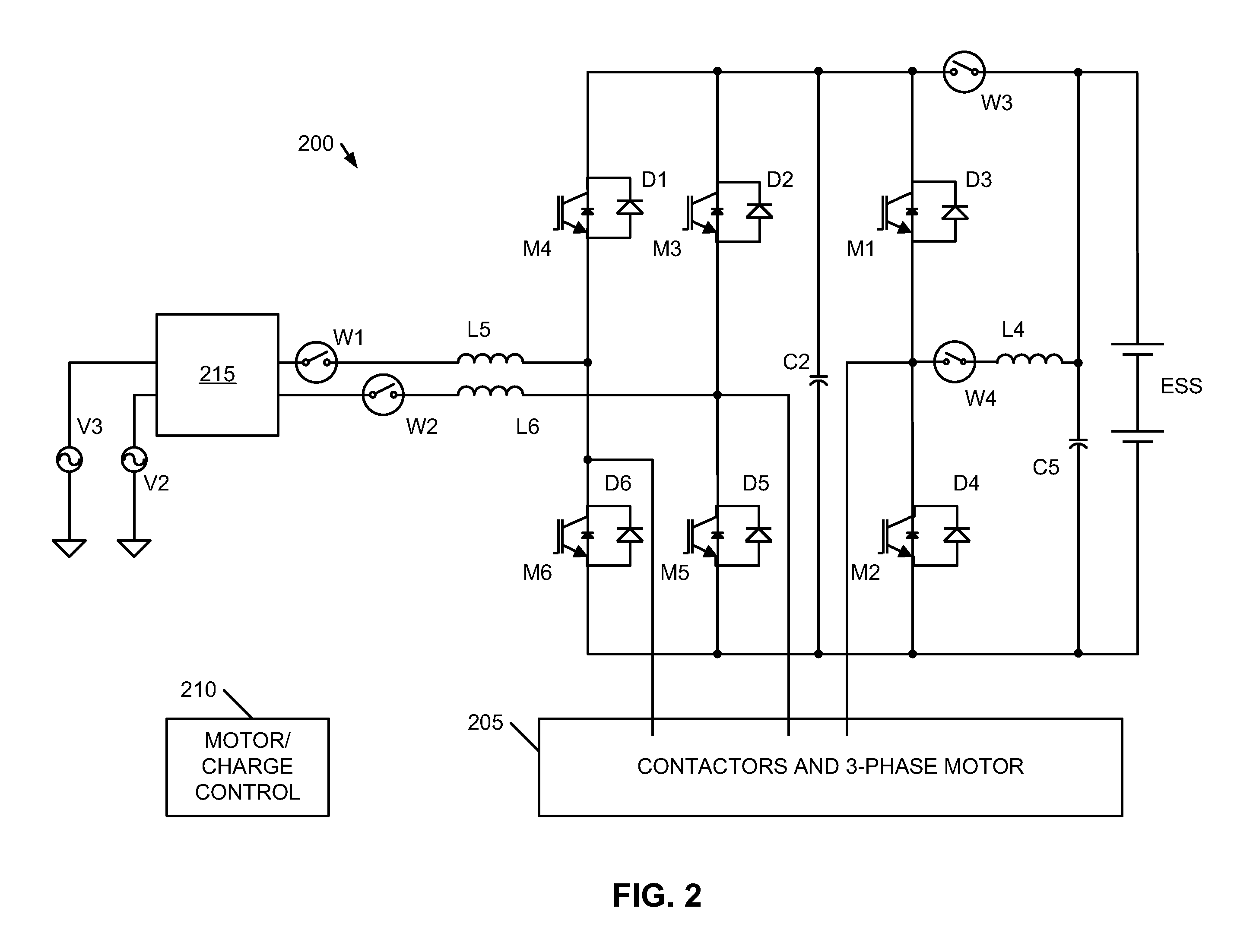
[0015]Embodiments of the present invention provide methods and systems for a voltage converter that is capable of providing high energy to a high performance energy storage assembly for charging the energy storage assembly while efficiently and safely handling conditions of large relative differences between a line-in voltage and voltage level of the energy storage assembly. The following description is presented to enable one of ordinary skill in the art to make and use the invention and is provided in the context of a patent application and its requirements. In the following text, the terms “energy storage assembly”“battery”, “cell”, “battery cell” and “battery cell pack”“electric double-layer capacitor” and “ultracapacitor” may be used interchangeably (unless the context indicates otherwise” and may refer to any of a variety of different rechargeable configurations and cell chemistries including, but not limited to, lithium ion (e.g., lithium iron phosphate, lithium cobalt oxide,...


PUM


Abstract

A charging method using a multiphase line voltage for charging an energy storage system (ESS) using a polyphase motor drive circuit communicated to a polyphase motor, the polyphase motor drive circuit including a plurality M of driver stages, one driver stage for each phase of the polyphase motor with each driver stage coupled across the energy storage system, the method including the steps of: (a) determining a charge mode responsive to a comparison of the multiphase line voltage to a voltage of the energy storage system, the determined charge mode including a boost mode when the voltage of the energy storage system has a first predetermined relationship to the multiphase line voltage and the determined charge mode including a boost-buck mode when the voltage of the energy storage system has a second predetermined relationship to the multiphase line voltage; (b) converting, when the charge mode includes the boost mode, the multiphase line voltage to a first charging voltage using a first set of N number of the plurality of driver stages, with N less than M, wherein the first charging voltage is communicated to the energy storage system, and wherein the first charging voltage is greater than the multiphase line voltage; and (c) converting, when the charge mode includes the boost-buck mode, the multiphase line voltage to a second charging voltage using a second set of P number of the plurality of driver stages when in the boost-buck mode, with P greater than N, wherein the second charging voltage is communicated to the energy storage system, and wherein the second charging voltage is less than the multiphase line voltage.

Description

BACKGROUND OF THE INVENTION[0001]The invention relates generally to charging of rechargeable energy storage systems (e.g., batteries and electric double-layer capacitors and the like) and more particularly to charging storage systems in conditions when a peak line voltage is greater than a storage system voltage, such as may be the case, for example, with a low state-of-charge (SOC) for the energy storage system.[0002]The voltage across the energy storage system varies as a function of SOC and line voltages used for recharging have an inherent variation as well. Relevant to this invention is the difference between the peak line voltage available to the charger and the voltage across the energy storage device being charged. In many high-energy applications (e.g., electric vehicles and industrial applications and the like), the energy storage system includes parallel and series connected cells and modules that have a net voltage greater than typical line voltages. In these typical cas...

Claims


Application Information

Patent Timeline
Patent Type & Authority Applications(United States)
IPC IPC(8): H02J7/00
CPCH01M10/44H02J7/00H02J7/007H02J7/02H02J7/022H02J7/0052H02J2207/20Y02E60/10H02J5/00
Inventor KRAUER, JEAN-PIERRE
Owner TESLA INC
Why Eureka
Try Eureka