Fairing for wind turbine blade

a technology of wind turbine blades and fairings, applied in the direction of propellers, propulsive elements, water-acting propulsive elements, etc., can solve the problems of power consumption during testing, and achieve the effect of reducing the energy consumption of wind turbine blade fatigue testing

Active Publication Date: 2012-01-26
VESTAS WIND SYST AS
View PDF4 Cites 17 Cited by
  • Summary
  • Abstract
  • Description
  • Claims
  • Application Information

AI Technical Summary

Benefits of technology

[0011]One object of the invention is to overcome or at least alleviate the above described problems. In particular, it is an object of the invention to reduce the energy consumption at wind turbine blade fatigue testing.
[0012]One way of achieving this object is by means of a fairing adapted to be mounted on a wind turbine blade, wherein the outer surface of said fairing is arranged so as to reduce, when mounted on the blade, the aerodynamic drag in a flapwise direction of the blade.

Problems solved by technology

A common concern related the above described tests, is the amount of power consumed during testing.

Method used


Image

  • Fairing for wind turbine blade
  • Fairing for wind turbine blade
  • Fairing for wind turbine blade

Examples


Embodiment Construction

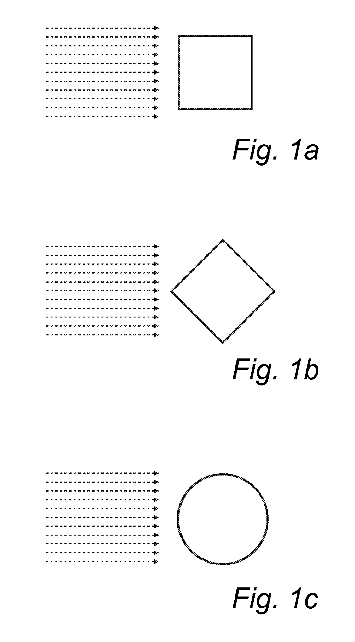
[0064]A streamlined shape is one with a contour that is itself a streamline, or its shape is such that its resistance to the flow of air, water, or another fluid past it is reduced. In other words, in order to streamline a body, the external contours are preferably smoothed out so that a streamlined flow over it is achieved and the flow's resistance to a motion of the body is reduced. This resistance may also be referred to as drag or form drag.

[0065]Calculations of the effect of a body's cross-section with respect to air resistance and drag, respectively can be found in aerodynamic reference tables. In general, the less of a body's surface that is oriented in a direction normal to the direction of the airflow, the smaller the air resistance and the drag.

[0066]The drag of a body with a constant square cross-section as illustrated in FIG. 1b and arranged in relation to the air flow as indicated in FIG. 1b, is lower than that of a body with a constant square cross-section as illustrat...


PUM


Abstract

The invention relates to a fairing adapted to be mounted on a wind turbine blade (2), wherein the outer surface of said fairing is arranged so as to reduce, when mounted on the blade, the aerodynamic drag in a flapwise (z) direction of the blade. In this way a reduction of the exciter power required in a flatwise fatigue test of the blade is achieved.

Description

TECHNICAL FIELD[0001]The current invention relates to a fairing for arrangement on a wind turbine blade or rotor blade, and to the use of said fairing at wind turbine blade testing and in particular at wind turbine blade fatigue testing.BACKGROUND[0002]According to one example a blade fatigue test to a wind turbine blade or a wind turbine rotor blade may comprise the following steps:[0003]the blade is bolted and / or clamped to a test rig and visually inspected,[0004]strain gauges are applied to the blade skin and wiring is done,[0005]an eccentric mass exciter and dead loads are mounted onto the blade to obtain the required cross sectional bending moments, and also to obtain R-ratios close to the required,[0006]a static calibration test is performed to obtain strain- and stiffness information for the blade in the cross sections equipped with strain gauges; the load level in terms of the bending moment range at the root interface is determined,[0007]the blade is subject to the required...

Claims


Application Information

Patent Timeline
Patent Type & Authority Applications(United States)
IPC IPC(8): F03D11/00
CPCF03D1/0633F05B2240/301Y02E10/721F05B2260/97G01M5/0016F05B2260/83F05B2220/602Y02E10/72
Inventor BARNSLEY, MALCOLM
Owner VESTAS WIND SYST AS
Why Eureka
Try Eureka