Intake unit

a technology of inlet unit and inlet, which is applied in the direction of combustion air/fuel air treatment, machines/engines, other domestic objects, etc., can solve the problems of difficult to ensure a sufficient volume, provide inconvenient matter, and difficult to apply a sufficient vibration to a portion, so as to avoid overlap, shorten welding time, and increase welding strength

Inactive Publication Date: 2012-01-26
ROKI CO LTD
View PDF1 Cites 11 Cited by
  • Summary
  • Abstract
  • Description
  • Claims
  • Application Information

AI Technical Summary

Benefits of technology

[0021]In the intake unit according to the present invention, an intake unit is composed of a first member, a second member and a third member, which are manufactured separately and then welded together under application of pressure, wherein a welded portion between the first member and the second member and a welded portion between the second member and the third member are positioned in an overlapped manner, and a first jig receiving surface is formed to the overlapped welded portion between the welded portion between the second member and the first member and the welded portion between the second member and the third member so as to avoid the overlapping therebetween. Therefore, even after the welding between the second member and the first member, the pressure applying jig and the slide jig are not separated in distance, so that sufficient vibration can be applied to a portion to be welded, thus increasing the welding strength and shortening the welding time.
[0022]In addition, in the intake unit of the present embodiment, the second member is a port formed with a branch pipe groove, the first member is a port cover provided with a branch pipe line formed by closing the branch pipe groove, and the third member is a chamber communicated with one end of the branch pipe line and provided with a tank chamber formed with an intake port through which an intake fluid is introduced, so that the intake unit is constituted as an intake manifold. Accordingly, in the case when the respective welded portions between the port cover, the port and the chamber are overlapped, there can be provided an intake manifold in which the welding vibration can be sufficiently applied to the respective welded portions, thus improving the welding strength and shortening the welding time.
[0023]Furthermore, in the intake unit of the present embodiment, since the first jig receiving surface is formed to the port, the first jig receiving surface is easily formed to a position at which the welded portion between the port and the port cover and the welded portion between the port and the chamber are not overlapped.
[0024]Furthermore, in the intake unit of the present embodiment, since the first jig receiving surface is formed to one end of the branch pipe groove opposing to another end thereof communicated with the tank chamber, and a rib is formed to the first jig receiving surface so as to project outward of the branch pipe groove in parallel with the welded surface between the port and the chamber. Accordingly, the pressure applying jig and the slide jig can abut against the outer surface of the intake unit, so that the inner peripheral surface of the branch pipe line is not damaged, at the vibration welding operation, by the pressure applying jig and the slide jig, and it is possible to provide an intake unit prevented from generating any foreign material at the vibration welding operation.
[0025]Still furthermore, according to the intake unit of the present embodiment, since the first slide jig receiving portion is formed to the chamber, the port and the chamber can be easily welded after the welding between the port and the port cover.
[0026]Still furthermore, according to the intake unit of the present embodiment, since the second slide jig receiving portion is formed to the port and the second jig receiving surface is formed to the port cover, the port and the port cover can be easily welded.

Problems solved by technology

According to the structure of the conventional intake manifolds mentioned above, for example, in the intake manifold disclosed in the Patent Document 1, the inner-side welding flange projects inside the branch pipe line, so that it is difficult to ensure a sufficient volume for the intake pipe line, and in addition, the smooth flow of the intake fluid is blocked by the inner-side welding flange, thus providing inconvenient matter.
Moreover, in the intake manifold shown in FIG. 6, the pressure applying jig 141 and the slide jig 142 are separated in location by the distance L, so that it is difficult to apply a sufficient vibration to a portion to be welded, and hence, a stable welding strength cannot be realized, resulting in increasing in welding time.

Method used


Image

  • Intake unit
  • Intake unit
  • Intake unit

Examples


first embodiment

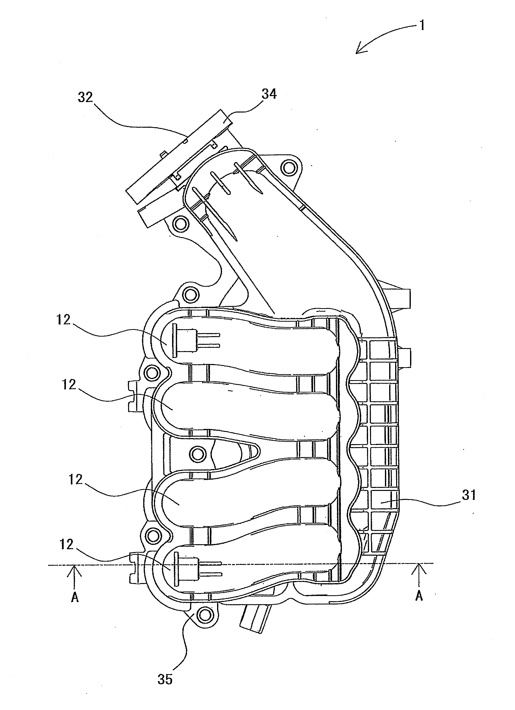
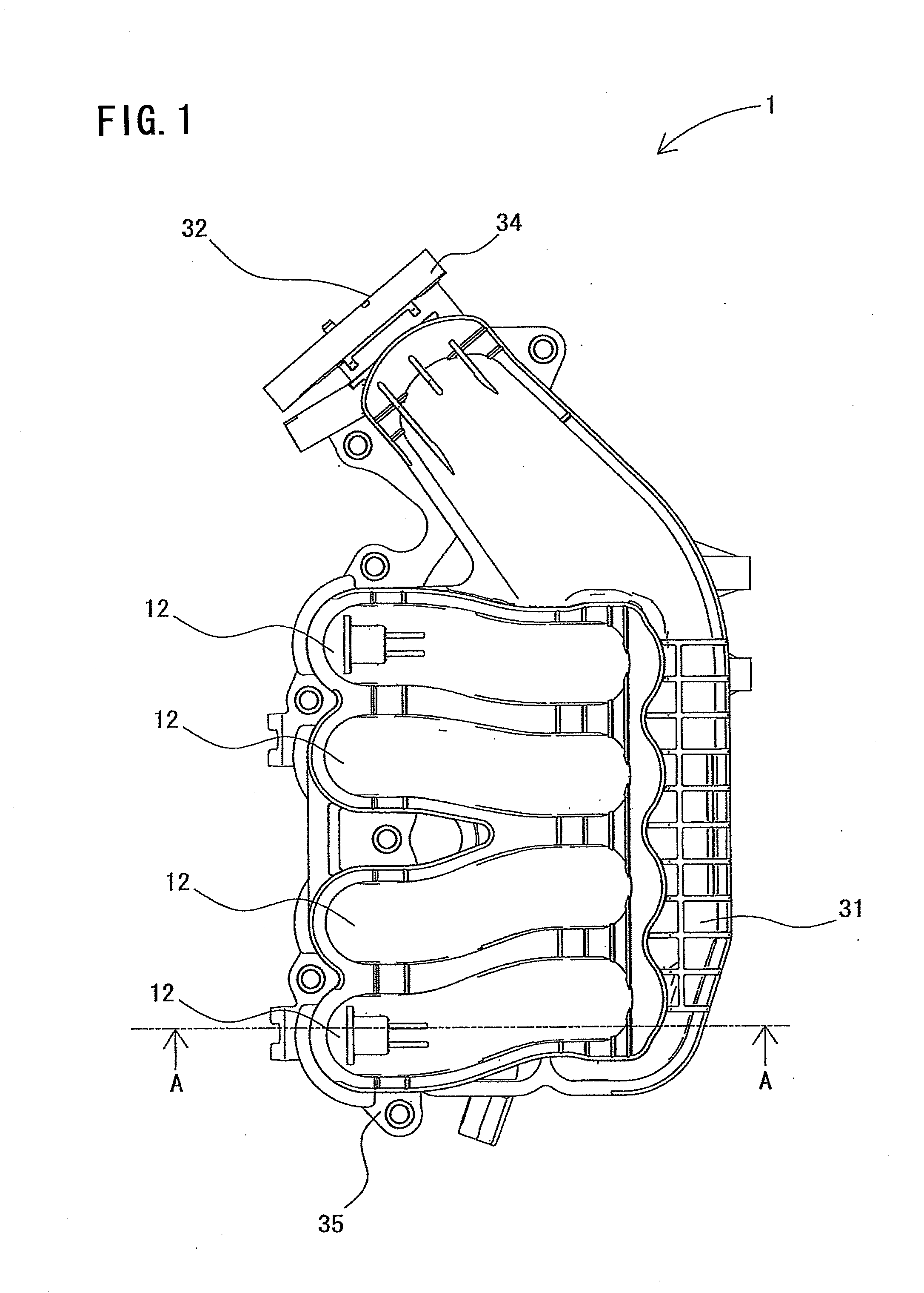
[0039]As shown in FIG. 1, an intake unit according to the first embodiment is represented as an intake manifold 1, which is provided with a tank chamber 31 formed with an intake port 32 through which an intake fluid is introduced and branch pipe lines (or merely pipe) 12 for distributing the intake fluid (i.e., fluid taken into the tank chamber 31) into respective cylinders of an internal combustion engine.

[0040]The intake manifold 1 of this embodiment is an intake manifold used for an inline four-cylinder engine, and hence, the four branch pipe lines 12 are equally formed. The intake port 32 is opened to the flanged portion 34 of the end portion of the tank chamber 31, and the intake manifold 1 is mounted to a throttle body for controlling intake fluid, not shown, through the flanged portion 34. One end of each of the branch pipe lines 12 opposing to the other one end continuous to the tank chamber 31 is formed with a flanged portion 35 of the internal combustion engine, not shown....

second embodiment

[0054]FIG. 5 is a sectional view for explaining the intake unit according to the second embodiment. Further, it is to be noted that the same reference numerals are added to members or portions corresponding to the same or similar ones constituting the intake unit as the first embodiment mentioned above and explanations thereof are hence omitted herein, and in the description with reference to FIG. 5, the width direction of the drawing is prescribed as lateral (right-and-left) direction.

[0055]As shown in FIG. 5, the intake unit according to this embodiment has a structure of a resonator 1a. The resonator 1a is a member utilized in connection with an intake system of an internal combustion engine so as to act to reduce intake noise generated at a time of introducing air from ambient atmosphere.

[0056]The resonator 1a has a housing constituting an outer casing, and the housing is composed of a cover 30a as a third member (parts or piece) constituting an upper half of the resonator 1a, a...


PUM

PropertyMeasurementUnit
pressureaaaaaaaaaa
volumeaaaaaaaaaa
strengthaaaaaaaaaa

Abstract

An intake unit includes a first member, a second member and a third member, which are manufactured separately and then welded together under application of pressure, wherein a welded portion between the first member and the second member and a welded portion between the second member and the third member are positioned in an overlapped manner, and a first jig receiving surface is formed to the overlapped welded portion between the welded portion between the second member and the first member and the welded portion between the second member and the third member so as to avoid the overlapping therewith.

Description

BACKGROUND OF THE INVENTION[0001]1. Field of the Invention[0002]The present invention relates to an intake unit, made or resin, composed of three separate members including first, second and third members which are welded by vibration welding process.[0003]2. Related Art[0004]A resin-made intake manifold is conventionally known as a member of part constituting an intake unit or system, which is manufactured by welding a plurality of parts or members through or by vibration welding process. Furthermore, it is desirable to integrally form a tank chamber such as resonator in terms of manufacturing steps, cost and so on in comparison with a method in which a tank chamber is formed separately.[0005]As mentioned, there are known various structures as intake manifolds made of resin in which each of the intake manifold is formed from a plurality of divided or separated parts or members for decreasing manufacturing step and cost increasing even by integrally providing a tank chamber.[0006]On...

Claims


Application Information

Patent Timeline
Patent Type & Authority Applications(United States)
IPC IPC(8): B32B3/00
CPCB29C65/069Y10T428/24479B29C66/1312B29C66/30223B29C66/322B29C66/543B29C66/71B29C66/73921B29L2031/7492F02M35/10321F02M35/10354F02M35/112B29C66/124B29K2077/00B29K2023/12B29C65/0618B29C66/301
Inventor OHTA, MASAHIROYANO, KENJI
Owner ROKI CO LTD
Why Eureka
Try Eureka