Real-time monitoring of retaining ring thickness and lifetime

Inactive Publication Date: 2012-01-26
APPLIED MATERIALS INC
View PDF8 Cites 23 Cited by
  • Summary
  • Abstract
  • Description
  • Claims
  • Application Information

AI Technical Summary

Benefits of technology

[0008]The invention generally provides a method and apparatus that facilitates monitoring of a retaining ring within a polishing system to determine condition of the retaining ring and/or assess lifetime of the retaining ring. In one embodiment, a method for monitoring at least one surface of a retaining ring coupled to a ca

Problems solved by technology

While the retaining ring is adapted to endure polishing of multiple substrates, the surfaces that are in contact with the polishing pad experience wear and periodic replacement of the retaining ring is necessary.
The conventional inspection methods are time-consuming, require personnel to physical

Method used


Image

  • Real-time monitoring of retaining ring thickness and lifetime
  • Real-time monitoring of retaining ring thickness and lifetime
  • Real-time monitoring of retaining ring thickness and lifetime

Examples


Embodiment Construction

[0023]The invention generally provides a method and apparatus that facilitates monitoring of a retaining ring within a polishing system to determine wear of the retaining ring and / or assess lifetime of the retaining ring. An on-tool monitoring device is described that provides monitoring of the retaining ring without the need to physically handle the retaining ring or shut down the polishing system. Additionally, data from the monitoring device may be provided to a controller and utilized for tuning subsequent polishing processes.

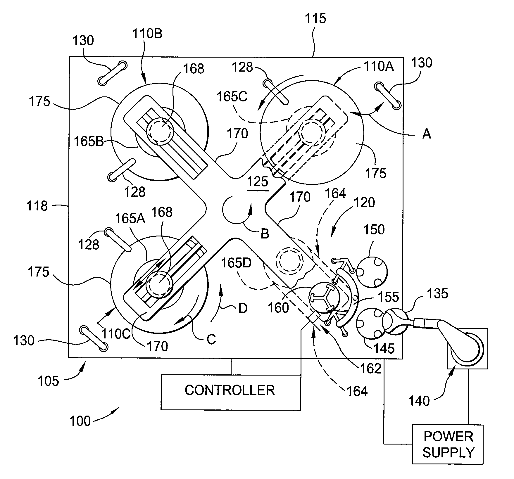
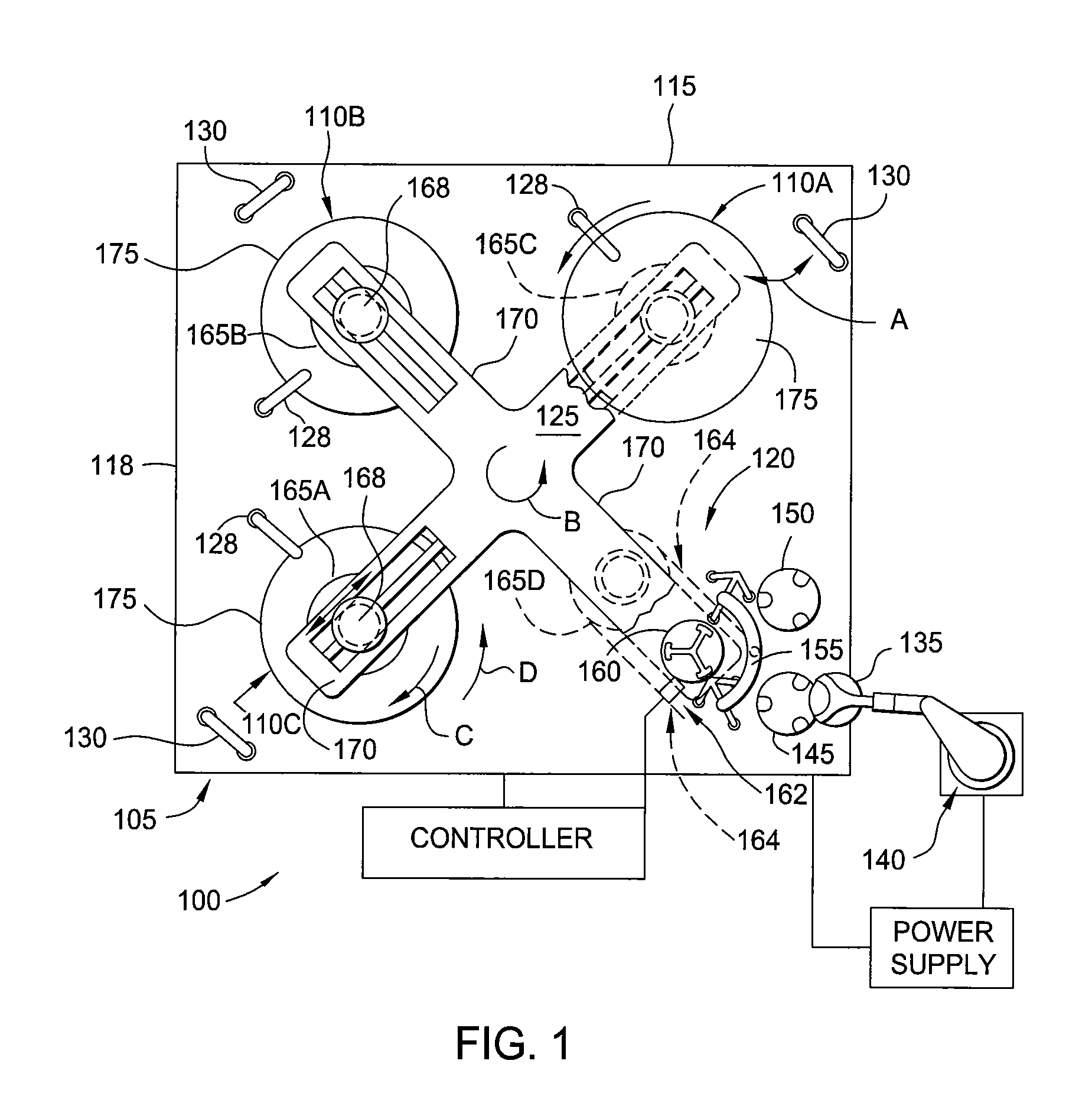
[0024]FIG. 1 is a plan view of a polishing system 100 having a polishing module 105 and a substrate transfer device that is suitable for electrochemical mechanical polishing and / or chemical mechanical polishing. The polishing module 105 includes a first polishing station 110A, a second polishing station 110B, and a third polishing station 110C disposed in an environmentally controlled enclosure 115. The substrate transfer device, such as a carousel 125, mov...


PUM


Abstract

A method and apparatus for monitoring the condition of a surface of a retaining ring disposed on a carrier head in a polishing module is described. In one embodiment, a method for monitoring at least one surface of a retaining ring coupled to a carrier head is provided. The method includes moving the carrier head adjacent a sensor device disposed in a polishing module, transmitting energy from the sensor device toward the retaining ring, receiving energy reflected from the retaining ring, and determining a condition of the retaining ring based on the received energy.

Description

BACKGROUND OF THE INVENTION[0001]1. Field of the Invention[0002]Embodiments of the invention relate to polishing systems for polishing a substrate, such as a semiconductor substrate. More particularly, to a method and apparatus for monitoring components of a polishing system.[0003]2. Description of the Related Art[0004]Chemical mechanical polishing (CMP) is one process commonly used in the manufacture of high-density integrated circuits to planarize or polish a layer of material deposited on a substrate. The substrate may be provided to a polishing station on a polishing system and retained in a carrier head that controllably urges the substrate against a moving polishing pad. CMP is effectively employed by providing contact between a feature side of the substrate and moving the substrate relative to the polishing pad while in the presence of a polishing fluid. Material is removed from the feature side of the substrate that is in contact with the polishing surface through a combinat...

Claims


Application Information

Patent Timeline
IPC IPC(8): B24B49/12
CPCB24B37/005B24B37/32B24B37/042B24B49/12H01L21/00H01L21/302H01L21/304H01L21/67242
Inventor MCREYNOLDS, PETERRONDUM, ERIC S.LEUNG, GARLEN C.ZHONG, ADAM H.MENK, GREGORY E.PRABHU, GOPALAKRISHNA B.OSTERHELD, THOMAS H.
Owner APPLIED MATERIALS INC
Why Eureka
Try Eureka