Method and Receiver for Estimating and Reporting a Channel Quality Measure

a wireless communication channel and quality measure technology, applied in the field of wireless communication channel quality measurement estimation and reporting, can solve the problems of unproportionally large degradation in coverage of high data rates within a limited bandwidth, high bandwidth utilization without corresponding reduction in power efficiency, and complex communication systems employed, so as to improve signal-to-noise/interference ratio, improve the effect of diversity and low fading correlation

Active Publication Date: 2012-01-26
TELEFON AB LM ERICSSON (PUBL)
View PDF6 Cites 81 Cited by
  • Summary
  • Abstract
  • Description
  • Claims
  • Application Information

AI Technical Summary

Benefits of technology

[0011]Selecting different antenna configurations at the receiver when determining channel quality measure is advantageous in that, for example, the antenna configurations may be used to provide additional diversity against fading on the communication channel. In respect of achieving additional diversity, a relevant feature of the different antenna configurations is the distance between the different antenna elements of each configuration as well as the number of antenna elements that are active in each configuration, i.e. the number of antennas that actually receive data. This is to a large extent due to the relation between the antenna distance(s) and to the mutual correlation between the channel fading experienced the by the signals at the different antennas. The different antenna configurations may also include antennas with different polarization directions, for further achieving a low fading correlation between the antenna configurations.
[0012]Moreover, the different antenna configurations may be used for “receive beam shaping” where the signal from each antenna may be amplified by applying different weighting patterns for achieving a desired sensitivity pattern. By doing this, noise in one particular direction may be ignored while signals in other direction are intercepted by the antennas, i.e. by the antenna configurations.
[0013]In case the transmi

Problems solved by technology

However, today more complex communications systems are employed, such as those making use of multiple-input multiple output (MIMO) and space-time coded systems, for which the channel quality measure may also be dependent on a receiver type in the user equipment.
However, in this case there is also the possibility to create multiple par

Method used


Image

  • Method and Receiver for Estimating and Reporting a Channel Quality Measure
  • Method and Receiver for Estimating and Reporting a Channel Quality Measure
  • Method and Receiver for Estimating and Reporting a Channel Quality Measure

Examples


Embodiment Construction

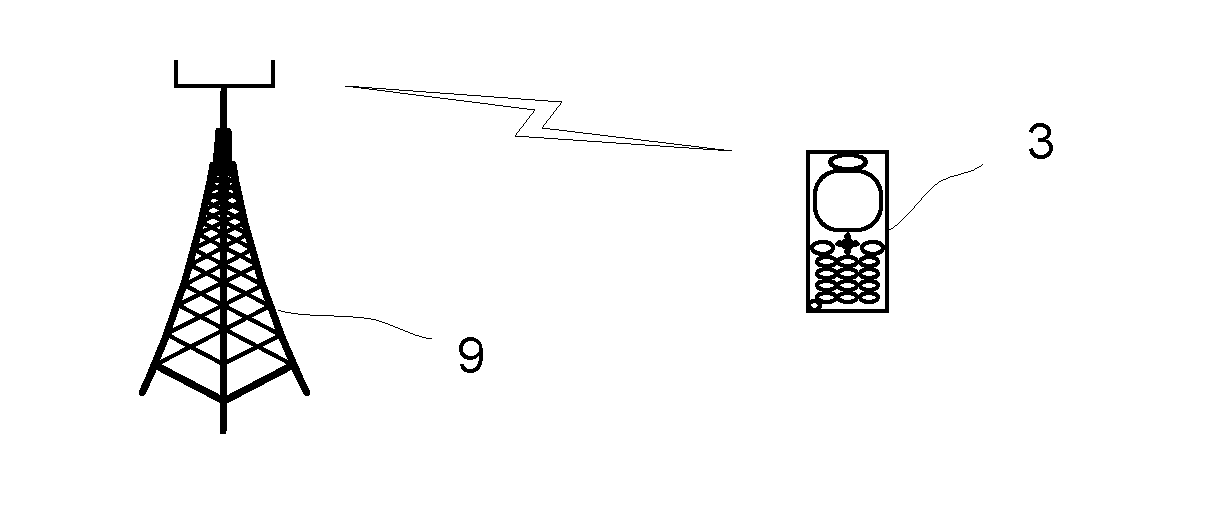
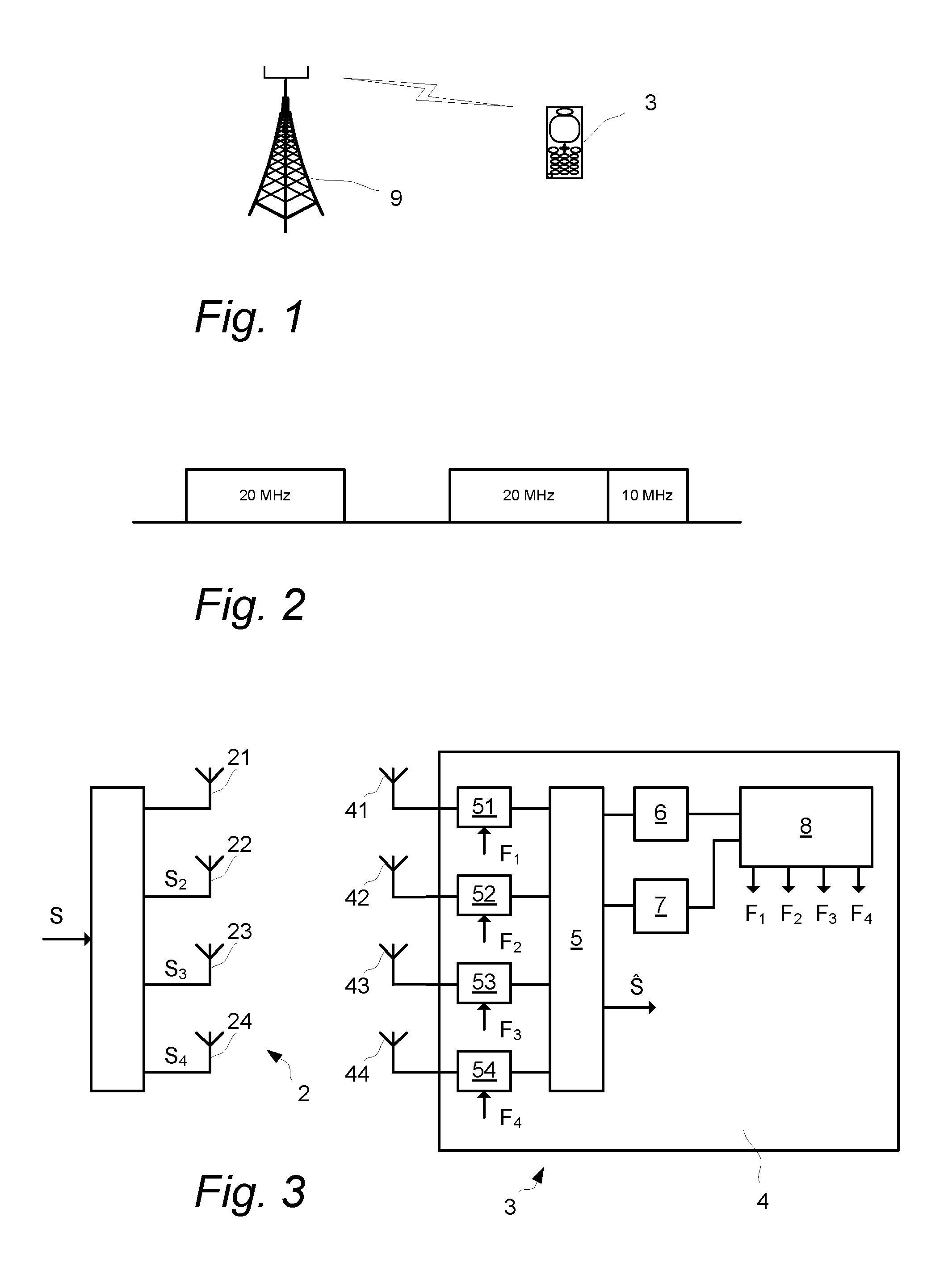
[0038]With reference to FIG. 1, a base station 9 and a user equipment 3 in the form of a cell phone are illustrated. Instead of a cell phone, the user equipment may be a PDA, a laptop, a modem, a TV or any other electronic equipment fitted with means for wireless communication via a wireless communication channel established between the user equipment 3 and the base station 9. The base station 9 is in turn connected to a conventional communication network (not shown).

[0039]Both the base station 9 and the user equipment 3 comprise means for spatial multiplexing, and more specifically MIMO antenna processing, and are each configured to fulfill the requirements of the 3G Long Term Evolution (3G LTE) proposal for a new mobile cellular. Multi-band transmission will be a principal part of the further releases of 3G Long term evolution (LTE) targeting ITU IMT-Advanced capabilities.

[0040]This means that contiguous and non-contiguous spectrums of frequency bandwidths (component bands) are us...


PUM


Abstract

A method of estimating and reporting, for a receiver (4) associated with a plurality of antennas (41, 42, 43, 44), a channel quality measure of a wireless communication channel from a transmitter (2) to the receiver, the method comprising the steps of: selecting at least one antenna configuration from a set of mutually different antenna configurations inherent to the receiver; determining a channel quality measure for the selected antenna configuration; and reporting the channel quality measure. The set of mutually different antenna configurations comprises antenna configurations that are allocated to different frequency bands (FB1,FB3). A receiver (4), user equipment, computer program and computer readable medium are also disclosed.

Description

TECHNICAL FIELD[0001]Embodiments according to the present invention relates to a method, a receiver, a computer readable medium and a user equipment for estimating and reporting a channel quality measure of a wireless communication channel.BACKGROUND ART[0002]In a wireless communication network a base station communicates with a user equipment (UE) which is actively located within an area of radio coverage of the base station and comprises a receiver for receiving signals from the base station. Some examples of user equipments include cell phones, PDA's, laptops, mobile broadband modems etc.[0003]User equipments are commonly at different locations within the area of radio coverage with correspondingly different received signal strength and interference levels. Consequently, some user equipments can receive data at much higher data rates than other user equipments. In order to optimally utilize the data transmission time, it is desirable to ensure that the base station transmits to e...

Claims


Application Information

Patent Timeline
IPC IPC(8): H04W24/10
CPCH04B7/0871H04W24/10H04B7/0874
Inventor WINTZELL, OLALINCOLN, BOLINDOFF, BENGT
Owner TELEFON AB LM ERICSSON (PUBL)
Why Eureka
Try Eureka