Filter device and liquid injection apparatus having the same

a filter device and liquid injection technology, applied in the direction of liquid degasification, separation process, filtration separation, etc., can solve the problems of blood vessel or brain of the patient, fatal danger, lowering the flow rate of injectable liquid, etc., to prevent the impurities of adhesive components, the effect of effectively removing air and impurities

Inactive Publication Date: 2012-01-26
E WHA FRESENIUS KABI
View PDF5 Cites 7 Cited by
  • Summary
  • Abstract
  • Description
  • Claims
  • Application Information

AI Technical Summary

Benefits of technology

[0041]According to the present invention, there are advantages in that the filter device can effectively remove air and impurities such as solid particles contained in a liquid such as a medicine, prevent the air in the medicine from flowing into an extension tube connected to the filter device, and ensure a maximum surface area of a hydrophilic filter for filtering off solid particles such as glass fragments so that a flow rate of a medicine passing through the filter device does not decrease.
[0042]In addition, it is possible to prevent impurities of adhesive components from flowing into the filter device and / or the capillary tube when the capillary in the extension tube is sealably connected to the filter device by an adhesive using a conventional method.

Problems solved by technology

Meanwhile, if impurities (for example, glass fragments generated in opening a glass ampoule) or air is injected together with an injectable liquid into the body of a patient, such impurities or air may damage the blood vessel or brain of the patient and cause a fatal danger.
However, the conventional filter device has a problem in that a flow rate of the injectable liquid is lowered since two filters 100b-1 and 100b-2 blocks the flow path of the injectable liquid.
In addition, the conventional filter device has a structural limit in that the air in the injectable liquid is not entirely discharged through the air discharge hole 100a-2-1 after passing through the gas permeable filter 100b-2, but partially flows into the extension tube 104.

Method used


Image

  • Filter device and liquid injection apparatus having the same
  • Filter device and liquid injection apparatus having the same
  • Filter device and liquid injection apparatus having the same

Examples


examples

[0057]Hereinafter, preferred embodiments according to the present invention will be described in detail with reference to the accompanying drawings. The following embodiments of the present invention are just to implement the present invention and are not intended to limit or restrict the scope of the present invention. All techniques easily conceivable by those skilled in the art from the detailed descriptions and embodiments of the present invention are interpreted as belonging to the scope of the present invention. The references cited herein are incorporated herein by reference.

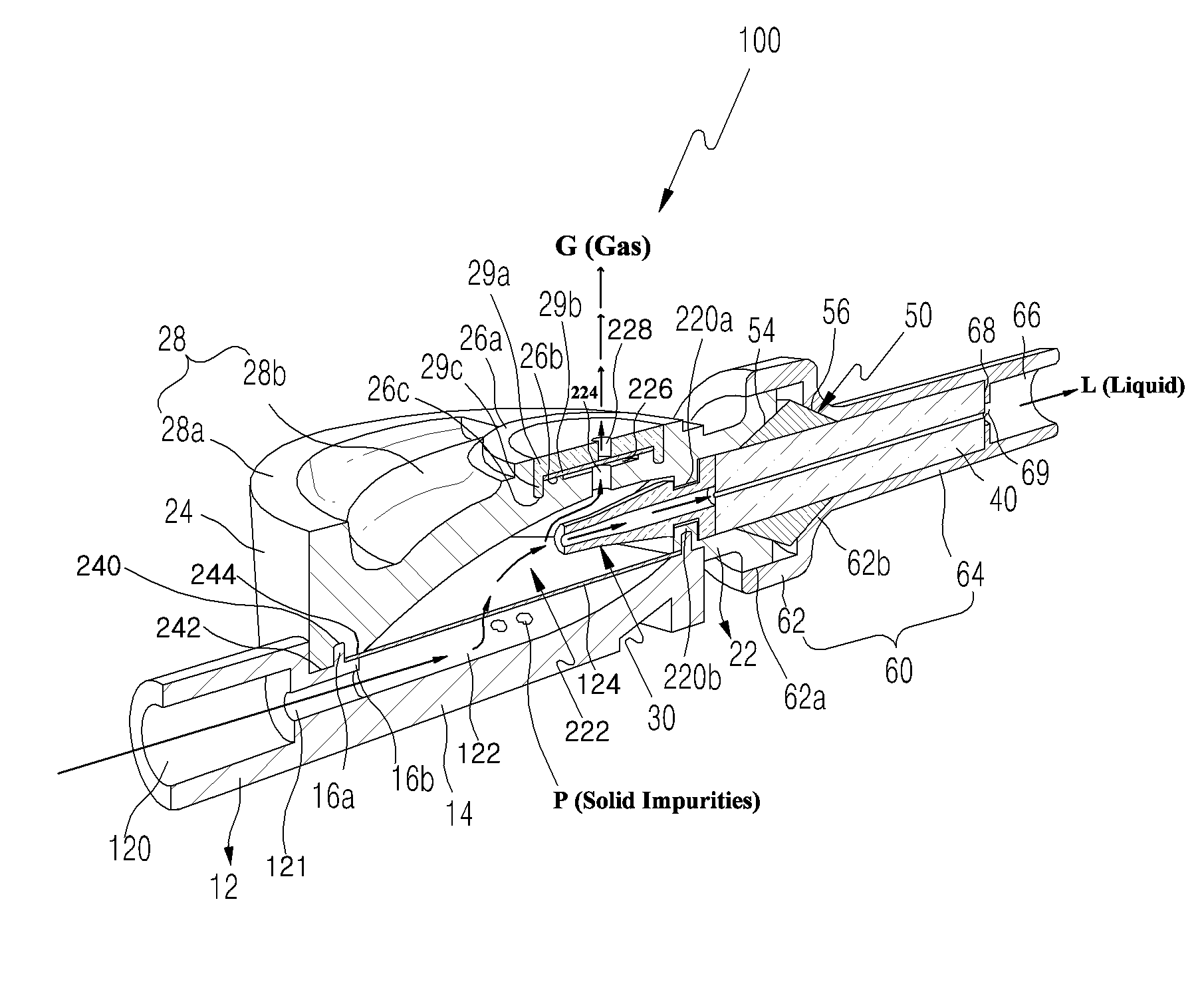
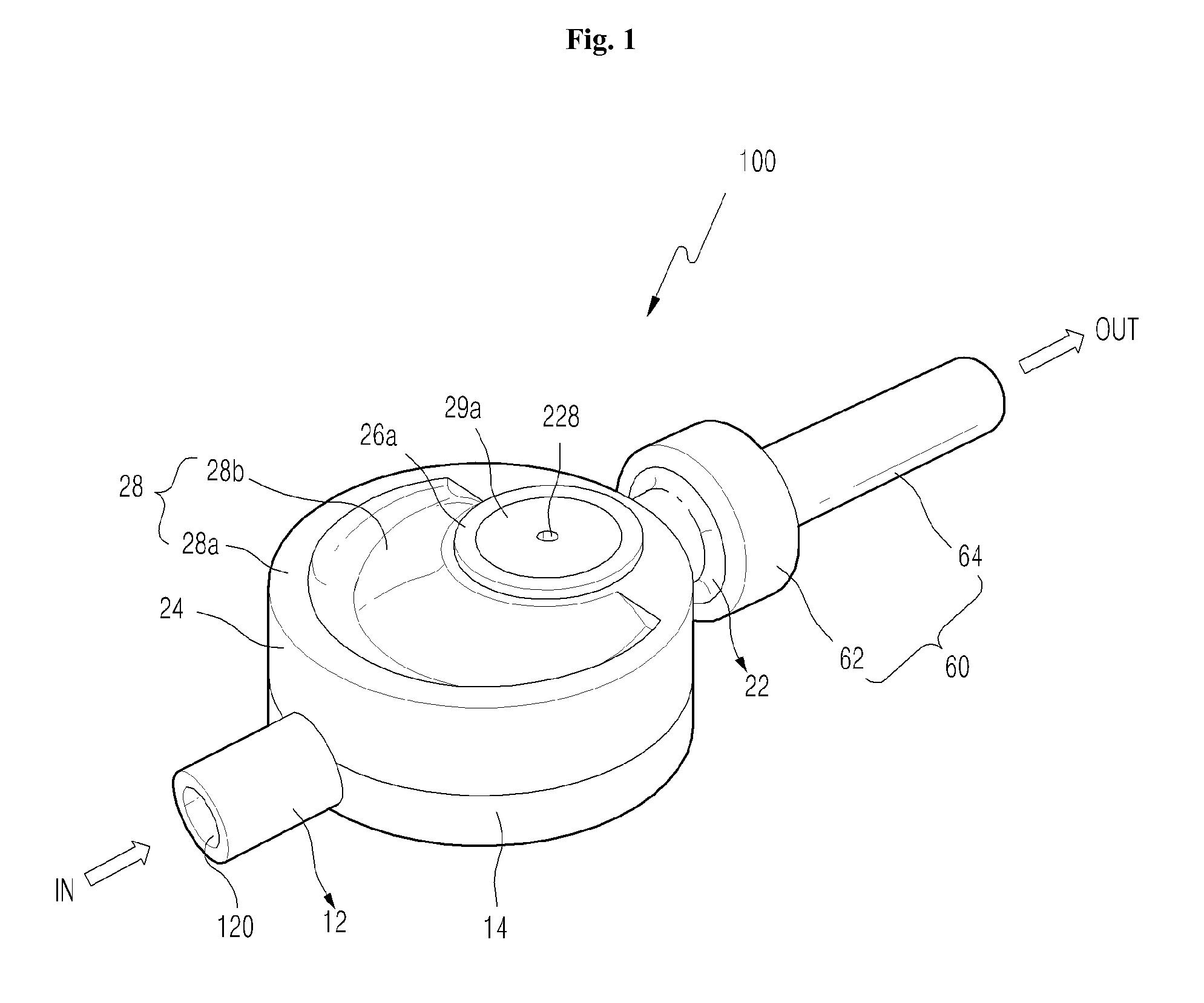
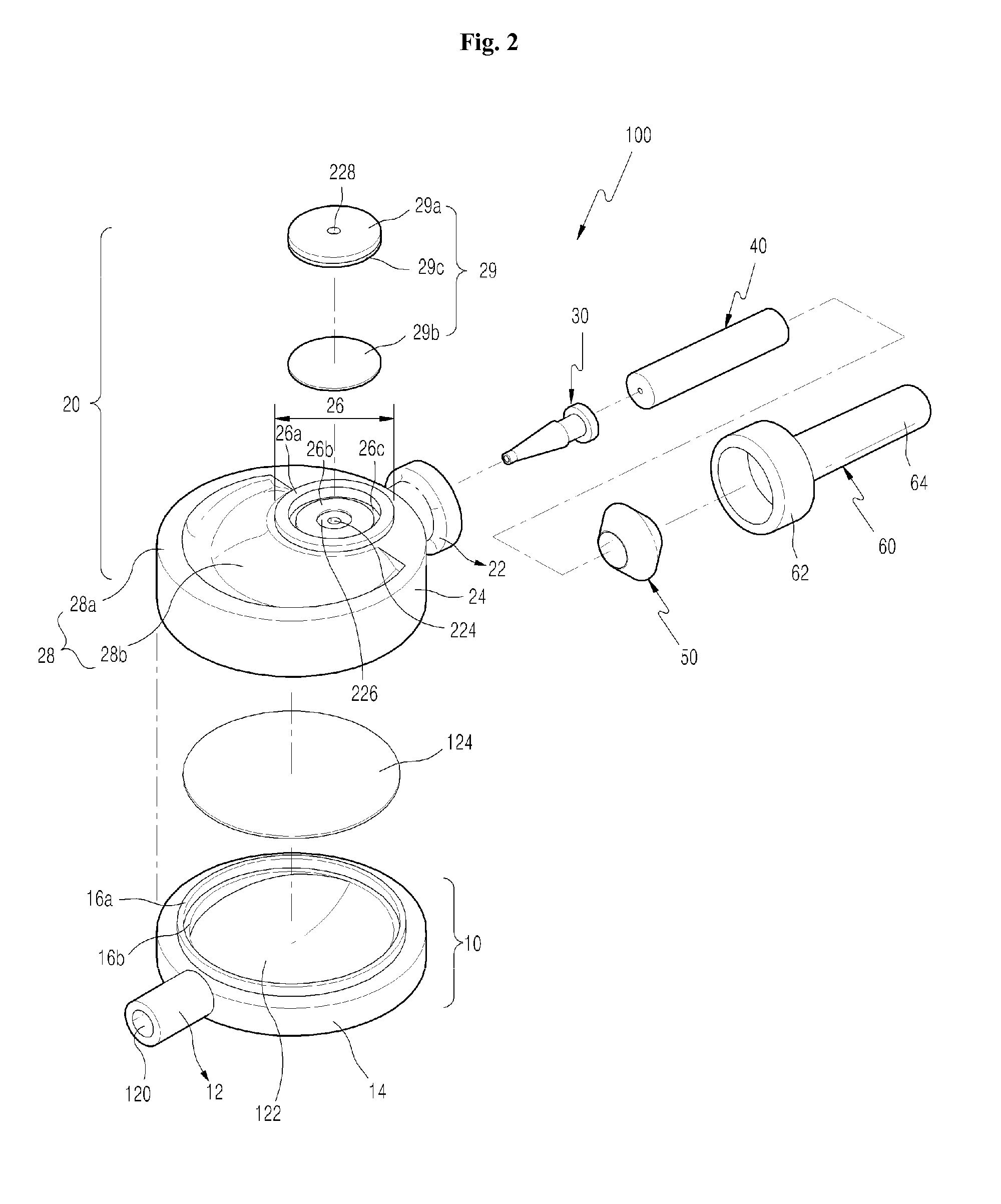
[0058]A filter device 100 according to a first embodiment of the present invention as shown in FIGS. 1 to 6 is installed between a tube connected to and extending from an IV (intravenous) bottle and an extension tube or a distal end connector to which an injection needle or catheter inserted into a patient is detachably coupled. As shown in FIG. 2, the filter device 100 of the first embodiment of the pres...


PUM

PropertyMeasurementUnit
inner diameteraaaaaaaaaa
inner diameter d2aaaaaaaaaa

Abstract

A filter device of the present invention includes a hydrophilic filter located in a vertical space in a filter housing to filter off solid impurities in an introduced liquid, at least one hydrophobic filter located corresponding to at least one gas discharge hole provided in the filter housing, the hydrophobic filter allowing gas in the introduced liquid to be discharged to the outside before and / or after the liquid passes through the hydrophilic filter, and a blocking member for preventing gas in the liquid passing through the hydrophilic filter from flowing into the outlet tube, the blocking member being installed in the filter housing to block the outlet tube, the blocking member having a longitudinal passage formed in a center portion thereof so that the liquid is introduced into the outlet tube through the passage and discharged therefrom. According to the present invention, there are advantages in that the filter device can effectively remove air and impurities such as solid particles contained in a liquid such as a medicine, prevent the air in the medicine from flowing into an extension tube connected to the filter device, and ensure a maximum surface area of a hydrophilic filter for filtering off solid particles such as glass fragments so that a flow rate of a medicine passing through the filter device does not decrease.

Description

TECHNICAL FIELD[0001]The present invention relates to a filter device, and more particularly, to a filter device which effectively removes air and impurities such as solid particles contained in a liquid such as a medicine, prevents the air in the medicine from flowing into an extension tube connected to the filter device, and ensures a maximum surface area of a hydrophilic filter for filtering off solid particles such as glass fragments so that a flow rate of a medicine passing through the filter device does not decrease.[0002]In addition, the present invention relates to a filter device which can prevent impurities of adhesive components from flowing into the filter device and / or a capillary tube when the capillary tube in the extension tube is sealably connected to the filter device by an adhesive using a conventional method.[0003]Further, the present invention relates to a liquid injection apparatus including such a filter device.BACKGROUND ART[0004]Generally, in many occasions,...

Claims


Application Information

Patent Timeline
Patent Type & Authority Applications(United States)
IPC IPC(8): A61M5/38B01D19/00B01D36/02
CPCA61M5/385A61M5/38A61M5/165A61M5/36
Inventor KIM, YONG-NYUN
Owner E WHA FRESENIUS KABI
Why Eureka
Try Eureka