Method and system for a turbocharged engine

Active Publication Date: 2012-02-02
FORD GLOBAL TECH LLC
View PDF21 Cites 76 Cited by
  • Summary
  • Abstract
  • Description
  • Claims
  • Application Information

AI Technical Summary

Benefits of technology

[0009]In this way, by flowing only a portion of the exhaust gas through the turbine while naturally aspirating the remaining portion of exhaust gas into the cylinder, heat recovered from the exhaust gas is increased and the thermodynamic efficiency of the turbine is improved. By naturally aspirating some fresh air into the engine cylinder while boosting the remaining portion, compressor work may be reduced, thereby

Problems solved by technology

However, the inventors herein have identified potential issues with such a system.
As one example, addition of an exhaust turbine to drive the compressor may destroy the intended functionality of the system.
Specifically, if a turbine were included in the common exhaust

Method used


Image

  • Method and system for a turbocharged engine
  • Method and system for a turbocharged engine
  • Method and system for a turbocharged engine

Examples


Embodiment Construction

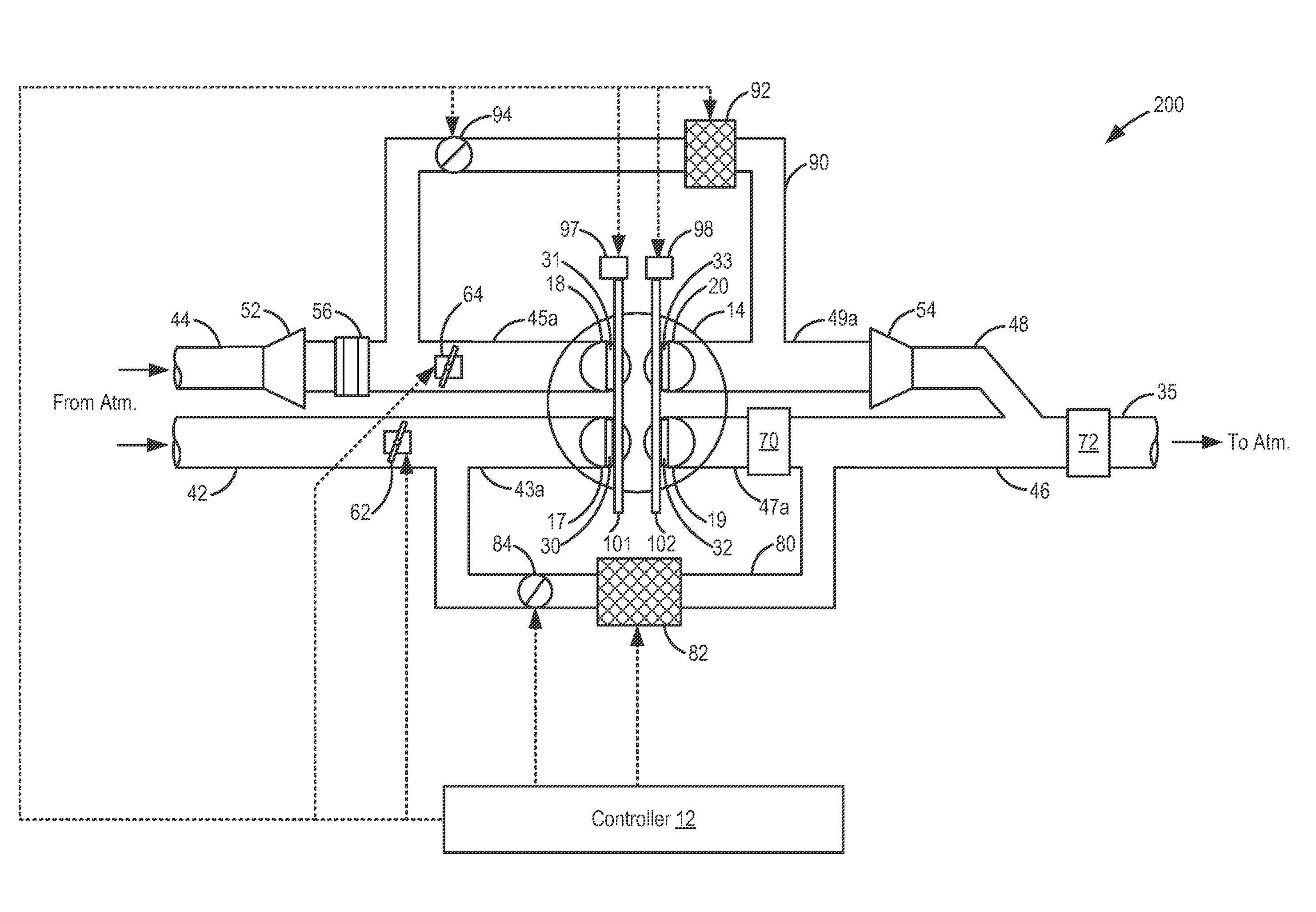
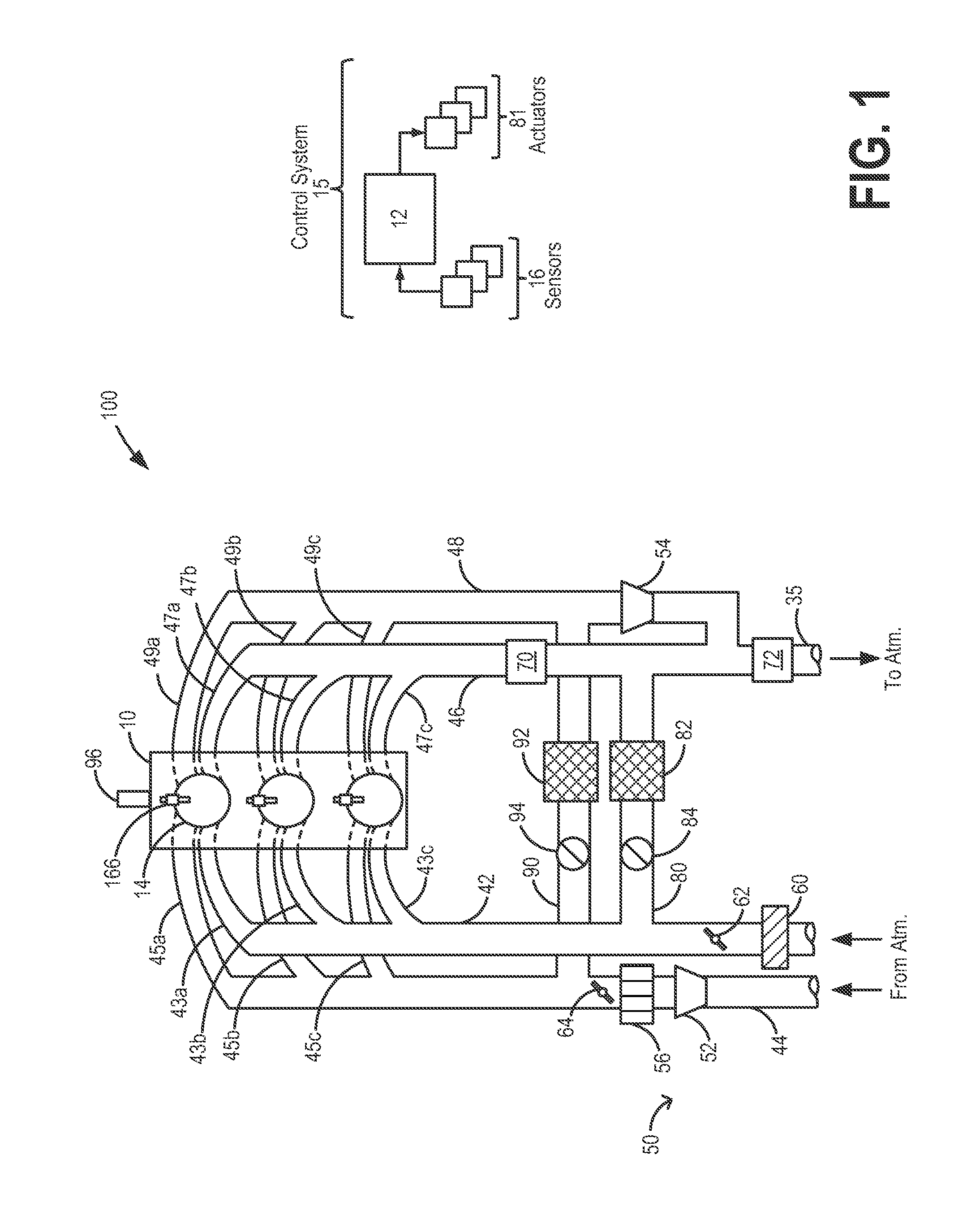
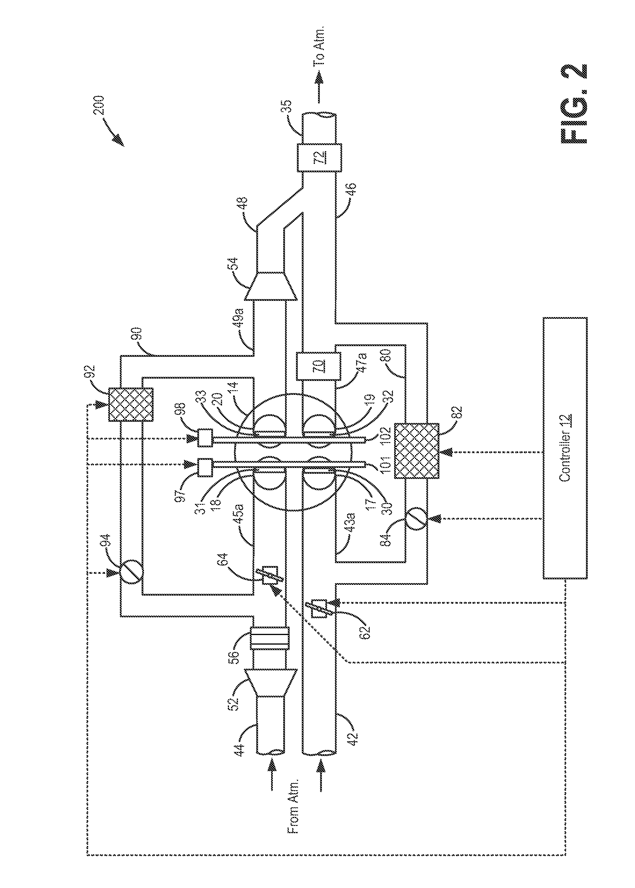
[0020]The following description relates to systems and methods for controlling an engine, such as the engine system of FIGS. 1-3, by providing aircharge of differing pressure and / or differing composition (e.g., different fresh air to EGR ratios) to an engine cylinder through distinct intake passages at different times in an engine cycle. Specifically, an intake aircharge at or below barometric pressure can be provided to the cylinder separate from an intake aircharge at compressor pressure. Likewise, an intake aircharge including recirculated exhaust gas can be provided to the cylinder separate from an intake aircharge having fresh air. Still other combinations may be possible, as elaborated in FIG. 6. An engine controller may be configured to perform a control routine, such as the routine of FIG. 4, to open a first cylinder intake valve at an earlier timing than a second cylinder intake valve (FIG. 5), thereby providing a first aircharge of a first composition at a different time i...


PUM


Abstract

Methods and systems are provided for a boosted engine having a split intake system coupled to a split exhaust system. Aircharges of differing composition, pressure, and temperature may be delivered to the engine through the split intake system at different points of an engine cycle. In this way, boost and EGR benefits may be extended.

Description

CROSS REFERENCE TO RELATED APPLICATIONS[0001]The present application is a continuation-in-part of U.S. patent application Ser. No. 12 / 878,838, entitled “Method and system for turbocharging an engine” filed Sep. 9, 2010, the disclosure of which is hereby incorporated by reference.FIELD[0002]The present description relates to a method for improving thermal efficiency of a turbocharged engine. The method may be particularly useful for providing EGR in a turbocharged engine.BACKGROUND AND SUMMARY[0003]Engine cylinders may be configured with one or more intake ports for receiving an aircharge. The one or more intake ports may diverge from a common intake passage or may have distinct intake ducts. Further, the one or more intake ports may receive fresh air or may recirculate exhaust gases.[0004]One example of a cylinder with a split intake system is shown by Duret in U.S. Pat. No. 6,135,088. Therein, at low load conditions, a first inlet port of the cylinder is configured to receive recir...

Claims


Application Information

Patent Timeline
IPC IPC(8): F02B47/08F02B37/00F02B33/44F02M25/07
CPCF01N13/02F01N13/009F02B37/00F02B2075/125F02D13/0207F02D13/0249F02D13/0257F02D41/0007F02D41/005F02D2041/001F02M25/0707F02M25/0732F02M25/0744F02M25/0748Y02T10/123Y02T10/144Y02T10/47Y02T10/18F02M35/1085F02M25/0711F01N13/107F02M26/05F02M26/24F02M26/38F02M26/42F02M26/08Y02T10/12Y02T10/40
Inventor PURSIFULL, ROSS DYKSTRAULREY, JOSEPH NORMAN
Owner FORD GLOBAL TECH LLC
Why Eureka
Try Eureka