Crankshaft and method for producing the same

a crankshaft and crankshaft technology, applied in the field of crankshafts, can solve the problems of insufficient cooling effect of crankshafts, and achieve the effects of reducing the amount of material disposed in forging die sets, reducing the load on forging die sets, and improving the service life of die sets

Inactive Publication Date: 2012-02-02
HONDA MOTOR CO LTD
View PDF1 Cites 18 Cited by
  • Summary
  • Abstract
  • Description
  • Claims
  • Application Information

AI Technical Summary

Benefits of technology

[0094]Not only weight reduction of the crankshaft 400, but also the following effects, can be obtained by forming the hollow holes 413A and 413B. FIG. 16 is a view showing a schematic structure of the arm 412 for explanation of an effect of weight saving by forming a hole. In FIG. 16, illustration of the holes 413A and 413B is omitted.
[0095]The amount of a material disposed in a forging die set can be reduced by forming the hollow holes 413A and 413B. Furthermore, the load on the die set in the forging can be reduced by lowering a height H of a counterweight 412A (shown in FIG. 16) by forming the hollow holes 413A and 413B. As a result, service life of the die set can be improved. By the above structure, forging cost can be reduced. According to an effect obtained by the weight saving of the holes 413A and 413B, the following structure is preferably applied to the holes 413A and 413B.
[0096]In the hole formed by a conventional technique, a cross-sectional shape thereof is circular or oval and a bottom surface is flat. In the crankshaft 400 of the present embodiment, the counterweight 412A is formed at the opposite side to the connecting portion of the crankpin 413 with respect to the journal shaft 411, so that the holes 413A and 413B are preferably formed at positions in which the crankpin and counterweight 412A can be balanced.
[0097]When a weight of the crankpin side portion is defined as “W1” and a position of the center of gravity thereof is defined as “R1”, and a weight of the counterweight side portion is defined as “W2” and a position of the center of gravity thereof is defined as “R2” (shown in FIG. 16), balancing amount between the crankpin 413 and the counterweight 412A can be expressed by an equality of the formula W1×R1=W2×R2. The counterweight 412A is a portion for obtaining dynamic balance, so that weight reduction of the counterweig

Problems solved by technology

In this case, the oil is cooled by an oil cooler,

Method used


Image

  • Crankshaft and method for producing the same
  • Crankshaft and method for producing the same
  • Crankshaft and method for producing the same

Examples


first embodiment

1. First Embodiment

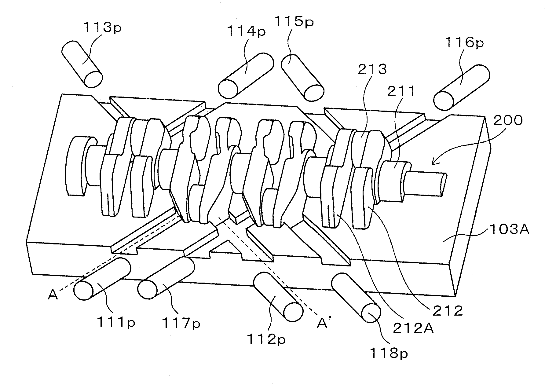
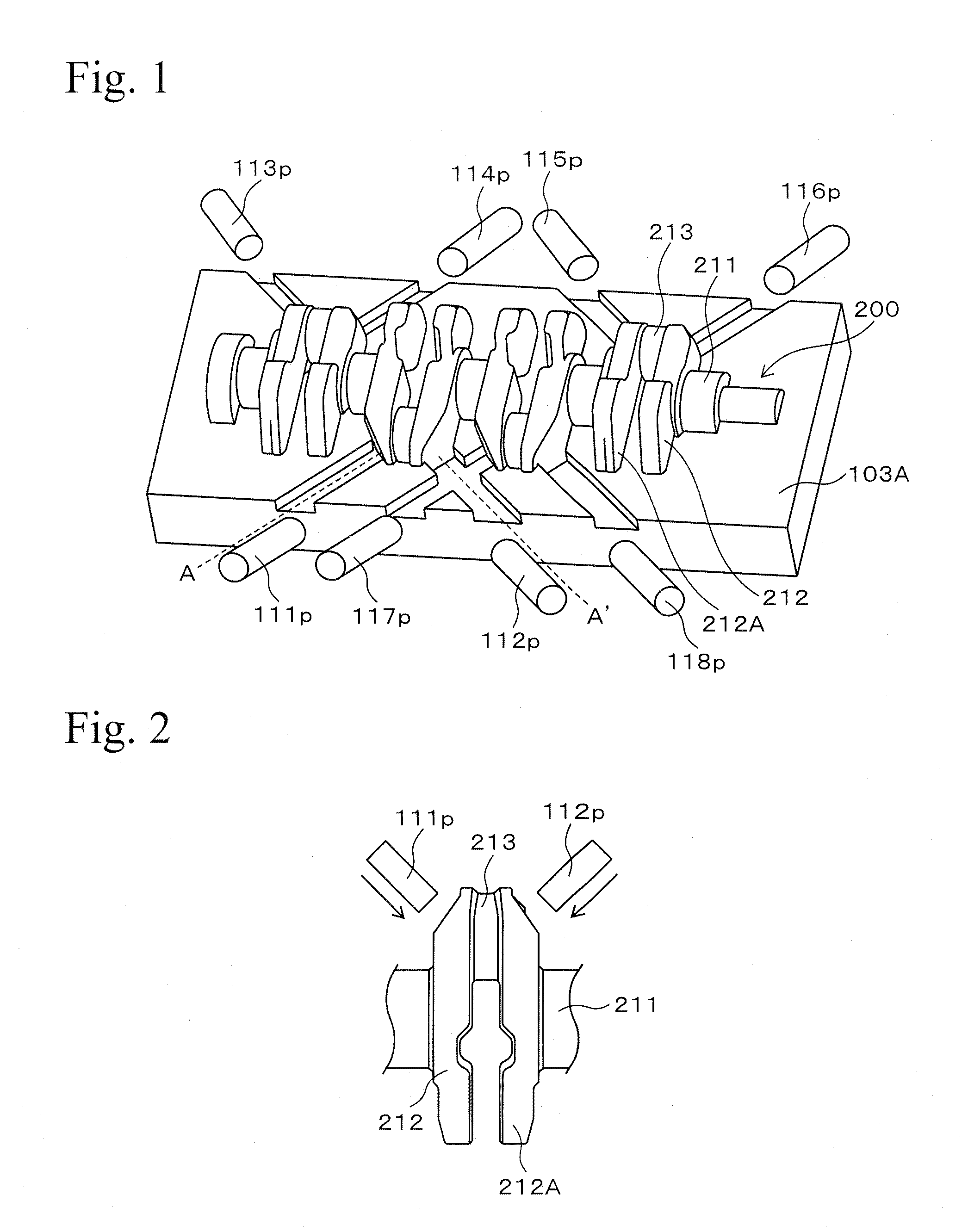
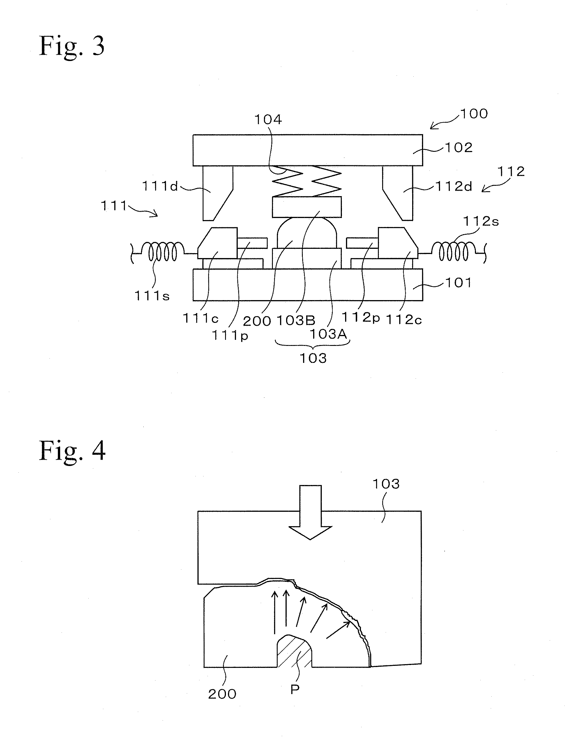
[0063]An embodiment of the present invention is explained with reference to Figures hereinafter. FIGS. 1 and 3 are conceptual diagrams showing a forging apparatus 100 used in a method for producing a crankshaft in accordance with the embodiment of the present invention. FIG. 3 is a diagram for explanation of forming a hole by the forging apparatus 100 shown in FIG. 1 and FIG. 2. FIG. 1 is a schematic view showing a lower die of the forging apparatus 100. FIG. 3 is a cross-sectional side view taken along a line A to A′ in FIG. 1 showing a schematic structure of the forging apparatus 100. In FIG. 3, each portion (in particular, a die set 103) of the forging apparatus 100 is simply shown.

[0064]The forging apparatus 100 is an example of an apparatus to which the method for producing the crankshaft of the present invention is applied and is an apparatus for obtaining a crankshaft for a four-cylinder engine. As shown in FIG. 3, the forging apparatus 100 is provided with...

second embodiment

2. Second Embodiment

2-1. Structure of Crankshaft

[0087]An embodiment of the present invention is explained with reference to the drawings hereinafter. FIG. 13 is a cross-sectional view showing a structure of a crankshaft 400 in accordance with the embodiment of the present invention. The crankshaft 400 is provided with a journal shaft 411 and a crankpin 413 parallel to the journal shaft 411 is connected thereto via an arm 412.

[0088]A counterweight 412A is formed at the arm 412 and a forming position of the counterweight 412A with respect to the journal shaft 411 is opposite side to a connecting position of the crankpin 413. Hollow holes 413A and hole 413B are formed at both sides of the crankpin 413. Fillets 414A and 414B are formed on journal shaft 411 side surfaces of boundaries between the crankpin 413 and the arm.

[0089]A journal shaft side through hole 421 for supplying an oil to a surface of the journal shaft 411 is formed in the journal shaft 411. A pin side through hole 422 fo...

example of embodiment

[0118]The present invention is explained in detail with reference to specific examples of the invention hereinafter. In the examples, forging was performed using the forging apparatus 100 of the present embodiment in a condition in which the maximum length of the clearance between the preformed product 200 of the crankshaft and the cavity of the die set 103 was set at 0 mm (Comparative Example 11), 0.5 mm (Experimental Example 11), and 1 mm (Comparative Example 12).

[0119]Experiment conditions were set as follows. A carbon steel was used as a material of the preformed product 200, a heating temperature in the forging was set at 1100 to 1300° C., an inserting angle θ of a punch (shown in FIG. 5A) was set at 45°, wall thicknesses K (shown in FIG. 5A) between a bottom surface of a hole 213L and an oil flow passage 223 or between a side surface of a hole 213M and the oil flow passage 223 was set at 6 to 10 mm, a distance L (non-interacting amount) between an inserting passage of the punc...


PUM

PropertyMeasurementUnit
Lengthaaaaaaaaaa
Lengthaaaaaaaaaa
Areaaaaaaaaaaa

Abstract

In a crankshaft 200, one hole 213L formed in a crankpin 213 has a bottom surface having a larger area and a depth from a surface of the crankpin less than those of another hole 213M. In forming the hole 213L and the hole 213M, a preformed product 200 of the crankshaft having a shape smaller than that of a cavity is disposed in a die set and punches are simultaneously inserted into the crankpin 213. By this operation, the hole 213L and the hole 213M are simultaneously formed in each crankpin 213 of the preformed product 200.

Description

BACKGROUND OF THE INVENTION[0001]1. Field of the Invention[0002]The present invention relates to a crankshaft and to a method for producing the same, and particularly relates to a technique for forming a hollow hole in a crankpin of the crankshaft.[0003]2. Related Art[0004]An internal-combustion engine is provided with, for example, a crankshaft 10 as shown in FIG. 10. The crankshaft 10 is provided with a journal shaft 11, and a crankpin 13 that is parallel to the journal shaft 11 is connected thereto via an arm 12. A counterweight 12A is formed at the arm 12, and a forming position of the counterweight 12A with respect to the journal shaft 11 is at the opposite side to a connecting position of the crankpin 13.[0005]In the journal shaft 11, a journal shaft side through hole 21 for supplying an oil to a surface of the journal shaft 11 is formed. In the crankpin 13, a pin side through hole 22 for supplying oil to a surface of the crankpin 13 is formed. The journal shaft side through h...

Claims


Application Information

Patent Timeline
IPC IPC(8): F16C3/14F16C3/08B23P15/00
CPCB21J5/02B21J13/025B21J13/03B21K1/08F16C3/08Y10T74/2185B21J9/027Y10T29/17Y10T74/2173Y10T29/49286F16C3/14
Inventor OHNUMA, TAKAYUKIANDO, TSUTOMUITO, YASUHIRO
Owner HONDA MOTOR CO LTD
Why Eureka
Try Eureka