Stump Grinding Tooth Assembly

a technology of tooth assembly and stump, which is applied in the direction of manufacturing tools, flat surfacing machines, rotary cutting tools, etc., can solve the problems of affecting the quality of grinding teeth, so as to reduce labor and reduce the cost to the lowest consumable cost, the effect of adding durability to the tooth assembly

Active Publication Date: 2012-02-02
LEONARDI MFG
View PDF10 Cites 14 Cited by
  • Summary
  • Abstract
  • Description
  • Claims
  • Application Information

AI Technical Summary

Benefits of technology

[0008]It is another object and advantage of the present invention to provide a tooth retaining clip that adds durability to the tooth assembly.
[0009]It is therefore a principal object and advantage of the present invention to provide a tooth assembly that reduces the labor associated with having to change a tooth on a grinding machine.
[0010]It is another object and advantage of the present invention to provide a tooth assembly that permits cutting bits to be replaced as opposed to having to replace an entire tooth, thereby lowering the cost to the lowest consumable.
[0011]Other objects and advantages of the present invention will in part be obvious and in part appear hereinafter.
[0012]In accordance with the foregoing objects and advantages, the present invention provides a spring clip that is affixed to a mounting block and is adapted to securely engage and retain a stump grinding tooth to the mounting block. The clip includes two pieces: a base and a spring member that is securely attached in cantilevered fashion to the base. The base comprises a flattened piece of material having a U-shaped groove defined between two legs that extend from the rearward section of the base. The spring member comprises a flattened piece of resilient material that overlays the base member and is riveted or otherwise affixed to the base member at its rearward section. The spring member further comprises a circular opening defined through a central part thereof with the leading part of the spring member being a

Problems solved by technology

Regardless of the type of mounting mechanism used, it takes a bit of time and tools to detach a worn or broken tooth from a mounting mechanism, and replace it with a new tooth.
While wood generally degrades the edge of the cutting bits, oftentimes they come into contact with foreign objects embedded in the wood, su

Method used


Image

  • Stump Grinding Tooth Assembly
  • Stump Grinding Tooth Assembly
  • Stump Grinding Tooth Assembly

Examples


second embodiment

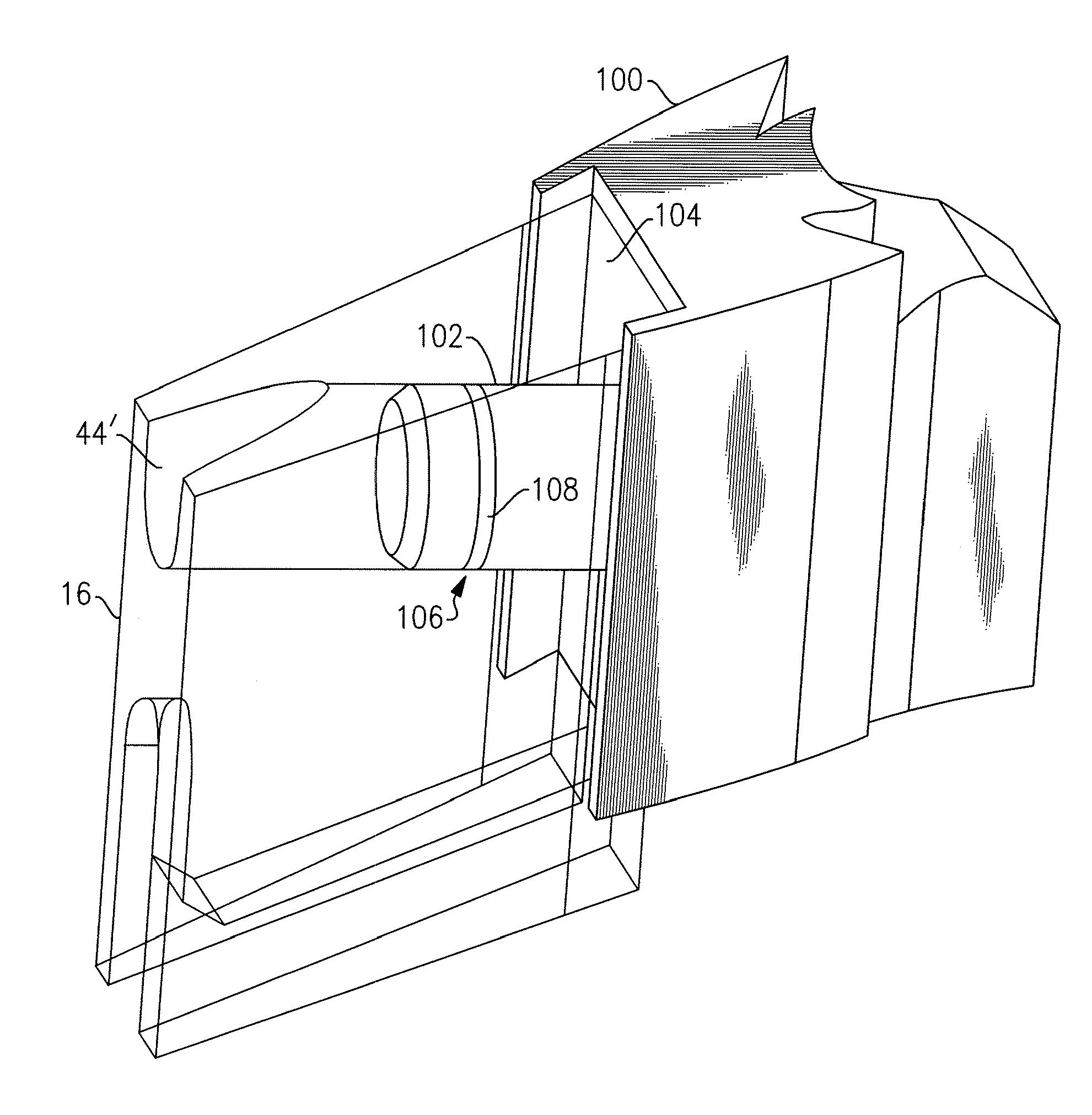
[0052]In the present invention shown in FIGS. 8 and 9A-D, a tooth 100 includes a post 102 extending outwardly from its upper surface 104. Post 102, which includes an annular groove 106 formed therein adjacent its free end and a sealing member 108, such as an O-ring, that is positioned in groove 106, is adapted to be inserted into opening 44′ formed in holder 16′. A fastening element (not shown) is inserted through opening 44′ and frictionally engages sealing member 108 in annular groove 106 to secure the interconnection between tooth 100 and holder 16′. To disassemble, an operator need only apply a pulling force to the end of the fastening member such that it disengages from annular groove 106.

third embodiment

[0053]In a third embodiment shown in FIG. 10, a tooth 200 is equipped with a male dovetail joint 202 formed on its upper surface 204 that interfaces with a corresponding female portion 210 formed in the lower surface of holder 16′. An opening formed in dovetail 202 is adapted to receive a threaded fastener 206, which can, for example, be in the form of a Phillips Head screw and that includes a retaining member 208 that securely engages the peripheral edge of wheel 12 and includes an angled extension that includes an opening through which fastener 206 passes and is positioned between the head of fastener 206 and holder 16′.

fourth embodiment

[0054]In a fourth embodiment shown in FIG. 11, a tooth 300 attaches directly to a wheel 12′ without a holder, but is nonetheless a quick-connect type of connection. In this embodiment, tooth 300 includes a body region with a first hole 302 formed therethrough and a second opening 304 (the opening 304 may be either open through the periphery of the tooth, as shown, or it may be a hole that is formed through the body region and is not open through the periphery of the tooth). A post 306 extends outwardly from opposing sides of wheel 12′ (actually a pair of posts, one from each side, extend along a common axis), and a slot 308 is formed through wheel 12′ a predetermined lateral distance from post 306. An axle 310 with opposed threaded ends, extends along an axis that is transverse to the plane of the wheel and through slot 308, and includes a medial body portion 312 that is shaped to snugly fit within and conform to the shape of slot 308. In addition, a shock absorbing member 314 is al...


PUM


Abstract

A stump cutting assembly mounted to a stump cutting wheel. Stump cutting assembly is a stump cutting tooth interconnected to the wheel by a holder or block that is fixed to wheel by welding or other equivalent process, an optional debris deflector and a fastener that interconnects tooth and deflector to holder. As wheel rotates about its axis of rotation, the tooth cuts away at wood or other debris in which it comes into contact through the side to side and/or longitudinal movement of a stump grinder unit.

Description

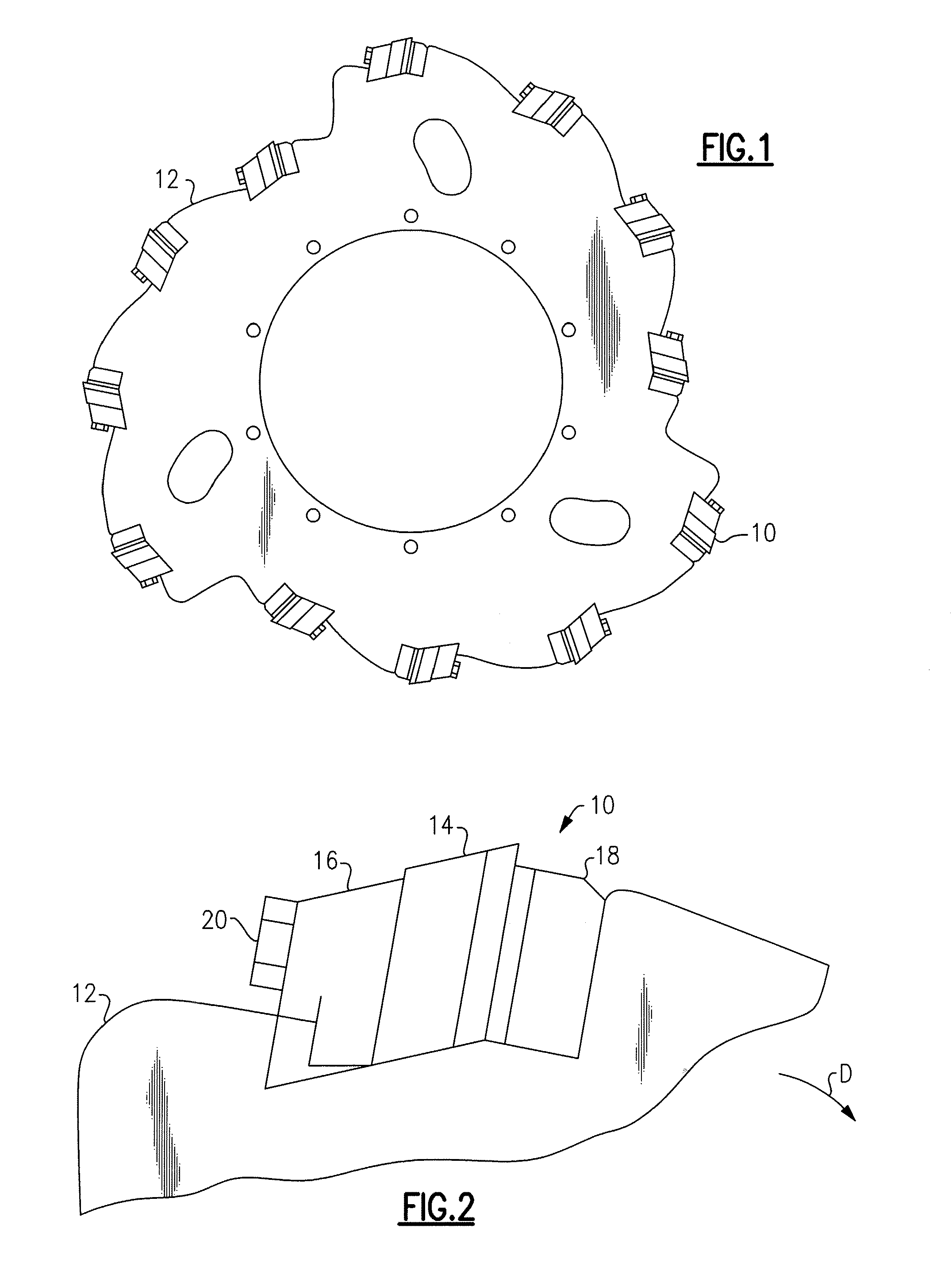
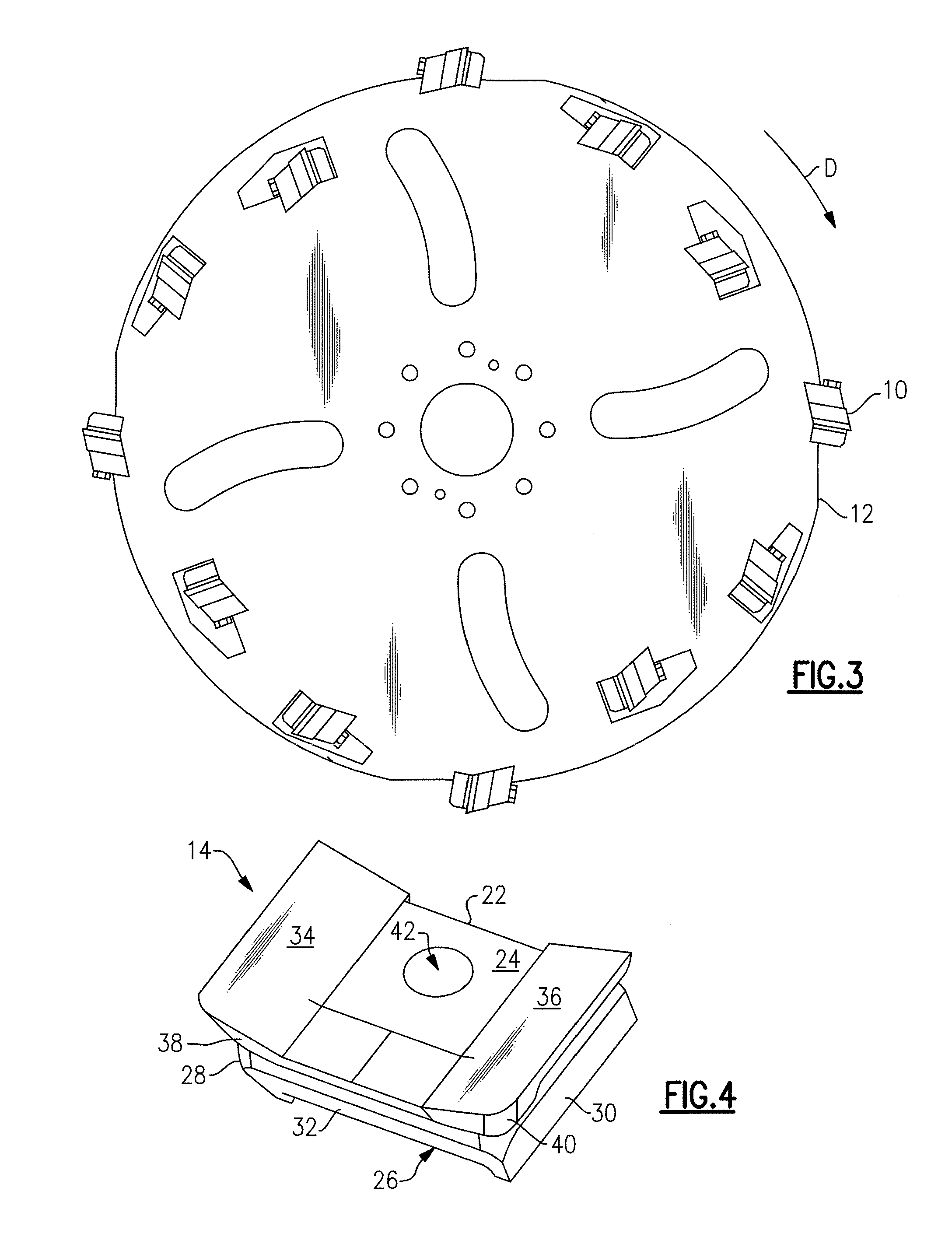
CROSS-REFERENCE TO RELATED APPLICATIONS[0001]The present application claims priority to PCT Number PCT / US2008 / 062900 which claims priority to U.S. Provisional Application No. 60 / 957,318, filed on Aug. 22, 2007, hereby incorporated by reference in its entirety.BACKGROUND OF THE INVENTION[0002]The present invention relates generally to stump grinding teeth, and more particularly to a mechanism for retaining a stump grinding tooth to a stump grinding tooth mounting mechanism.[0003]Stump grinders are well known in the art. These machines typically comprise a stump grinding wheel that is mounted for rotary motion to a chassis and driven by a motor. A plurality of stump grinding teeth are mounted to the wheel in annularly spaced relation to one another, either to the side surfaces of the wheel or to the peripheral edge of the wheel. In either event, a mounting mechanism is used to fix the tooth relative to the wheel.[0004]In its most basic embodiment, a pocket clamps a tooth to the wheel ...

Claims


Application Information

Patent Timeline
IPC IPC(8): A01G23/06
CPCB23D61/06A01G23/067B27G13/10
Inventor LEONARDI, JOSEPHJORDAN, BRUCE C.
Owner LEONARDI MFG
Why Eureka
Try Eureka