Cleaving method for a glass film

a technology of cleaving method and glass film, which is applied in the field of cleaving and dividing, can solve the problems of marked deterioration in glass strength, difficult to employ such a method of cleaving glass substrate with bending stress, and significant difficulty in forming scribe lines with respect to glass substrates, so as to avoid interference between cleaved surfaces

Active Publication Date: 2012-02-02
NIPPON ELECTRIC GLASS CO LTD
View PDF22 Cites 48 Cited by
  • Summary
  • Abstract
  • Description
  • Claims
  • Application Information

AI Technical Summary

Benefits of technology

[0026]As described hereinabove, according to the present invention, it is possible to provide a cleaving method for a glass film, by which the stable cleaving work with respect to the glass film can be continuously performed while interference between the cleaved surfaces is avoided.

Problems solved by technology

However, it is significantly difficult to form the scribe line with respect to the glass substrate thinned to become a state of a glass film.
Therefore, it is difficult to employ such a method of cleaving the glass substrate with a bending stress.
Further, defects formed in cleaved surfaces (for example, lateral cracks) may cause a problem of marked deterioration in strength of glass.
In addition, when the glass film is required to be continuously cleaved while being successively conveyed, there is also a problem that it is difficult to continuously cause a bending stress to act on the scribe line formed with respect to the glass film.

Method used


Image

  • Cleaving method for a glass film
  • Cleaving method for a glass film
  • Cleaving method for a glass film

Examples


first embodiment

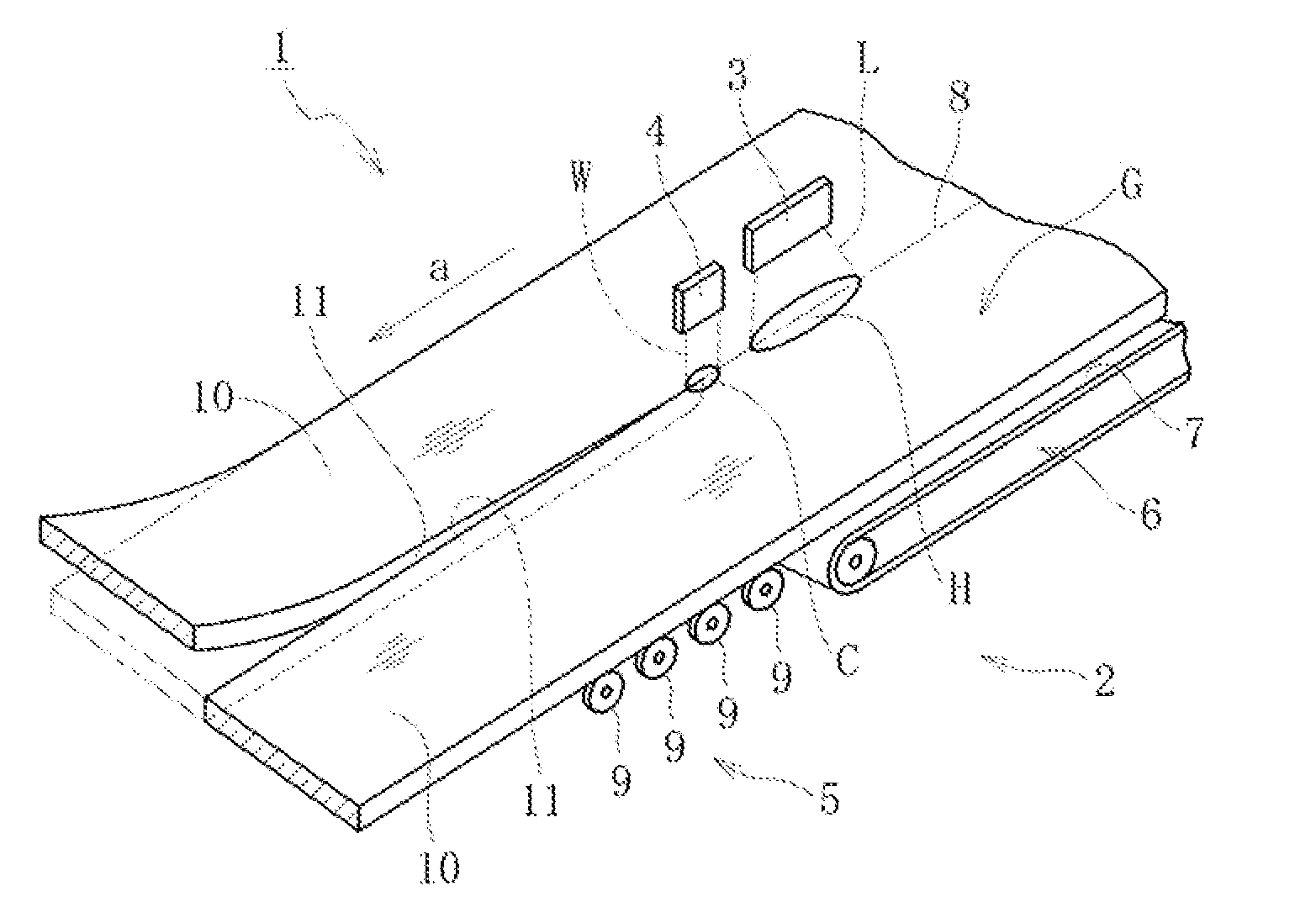
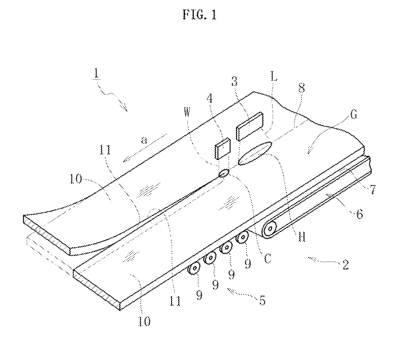
[0039]FIG. 1 is a schematic perspective view of a cleaving apparatus for carrying out a cleavingmethod for a glass film according to the present invention. The cleaving apparatus 1 mainly includes conveyance means 2 for conveying a glass film G toward a predetermined conveying direction “a”, locally heating means 3 for performing localized heating by applying a laser L to the glass film G placed in a lateral posture (for example, horizontal posture) on the conveyance means 2 from a front surface side of the glass film G, cooling means 4 for jetting cooling water W on a locally heated region H heated by the locally heating means 3 from the front surface side of the glass film G, and clearance forming means 5 described below.

[0040]Note that, in this embodiment, a carbon dioxide laser is used as the locally heating means 3, but alternatively, there may be used means capable of performing another type of localized heating such as heating with a heating wire or hot air blast. Further, th...

second embodiment

[0058]FIG. 9 is a schematic view illustrating a cleaving method for a glass film according to the present invention, in which the glass film G cleaved by the cleaving method is viewed in plan view. As illustrated in FIG. 9, in this embodiment, the clearance forming means 5 includes an entire-region heating device (not shown) for heating the entire widthwise region of the uncleaved glass film G with use of the thermal stress generated by localized heating and cooling, and an entire-region cooling device (not shown) for cooling the entire widthwise region of all the divided glass films 10 obtained by the cleaving. The heating and cooling devices generate a heated region 21 over the entire widthwise region of the uncleaved glass film G and a cooled region 22 over the entire widthwise region of all the cleaved divided glass films 10. Then, by setting a temperature difference between the heated region 21 and the cooled region 22 thus generated to a predetermined value or to fall within a...


PUM

PropertyMeasurementUnit
sizeaaaaaaaaaa
sizeaaaaaaaaaa
sizeaaaaaaaaaa

Abstract

Provided is a cleaving method for a glass film (G) including: cleaving, during conveyance of the glass film (G) in a predetermined direction, the glass film (G) continuously along a preset cleaving line (8) extending in a predetermined conveying direction (a) by a thermal stress generated through localized heating performed along the preset cleaving line (8) and through cooling of a locally heated region (H); dividing the glass film (G) in a width direction of the glass film (G) ; diverting, after the dividing, adjacent divided glass films (10) , which are obtained by the dividing, so that the adjacent divided glass films (10) are separated in a front and rear direction of the adjacent divided glass films; and forming a predetermined widthwise clearance between the adj acent divided glass films after the dividing of the glass film (G) and before the diverting of the adjacent divided glass films (10).

Description

TECHNICAL FIELD[0001]The present invention relates to a technology for cleaving and dividing, during conveyance of a glass film, the glass film in a width direction by a thermal stress generated through localized heating performed along a preset cleaving line extending in the conveying direction and through cooling of a region heated by the localized heating.BACKGROUND ART[0002]As is well known, flat panel displays (FPDs) have become mainstream as image display devices in recent years, the FPDs being typified by a liquid crystal display, a plasma display, an OLED display, and the like. Further, reducing the weight of those FPDs has been promoted. Therefore, currently, thinning of glass substrates used for the FPDs (forming the glass substrates as glass films) is promoted.[0003]Further, there is a growing use of an OLED as a plane light source, such as a light source for interior illumination, which emits only monochrome (for example, white) light, unlike a display that uses TFTs to ...

Claims


Application Information

Patent Timeline
Patent Type & Authority Applications(United States)
IPC IPC(8): B65H35/10
CPCB28D1/221C03B35/189C03B33/091Y02P40/57Y10T225/12
Inventor MATSUMOTO, YASUHIROMORI, KOICHINARUSE, HIROSHIETA, MICHIHARUMORI, HIROKI
Owner NIPPON ELECTRIC GLASS CO LTD
Why Eureka
Try Eureka