Ion detector
a technology of detectors and ion beams, applied in the field can solve the problems of reducing the detection efficiency of negative ions, reducing and difficulty in performing both attraction of negative ions, so as to improve the incidence efficiency of positive ions and improve the s/n ratio of ion beam detectors.
- Summary
- Abstract
- Description
- Claims
- Application Information
AI Technical Summary
Benefits of technology
Problems solved by technology
Method used
Image
Examples
first embodiment
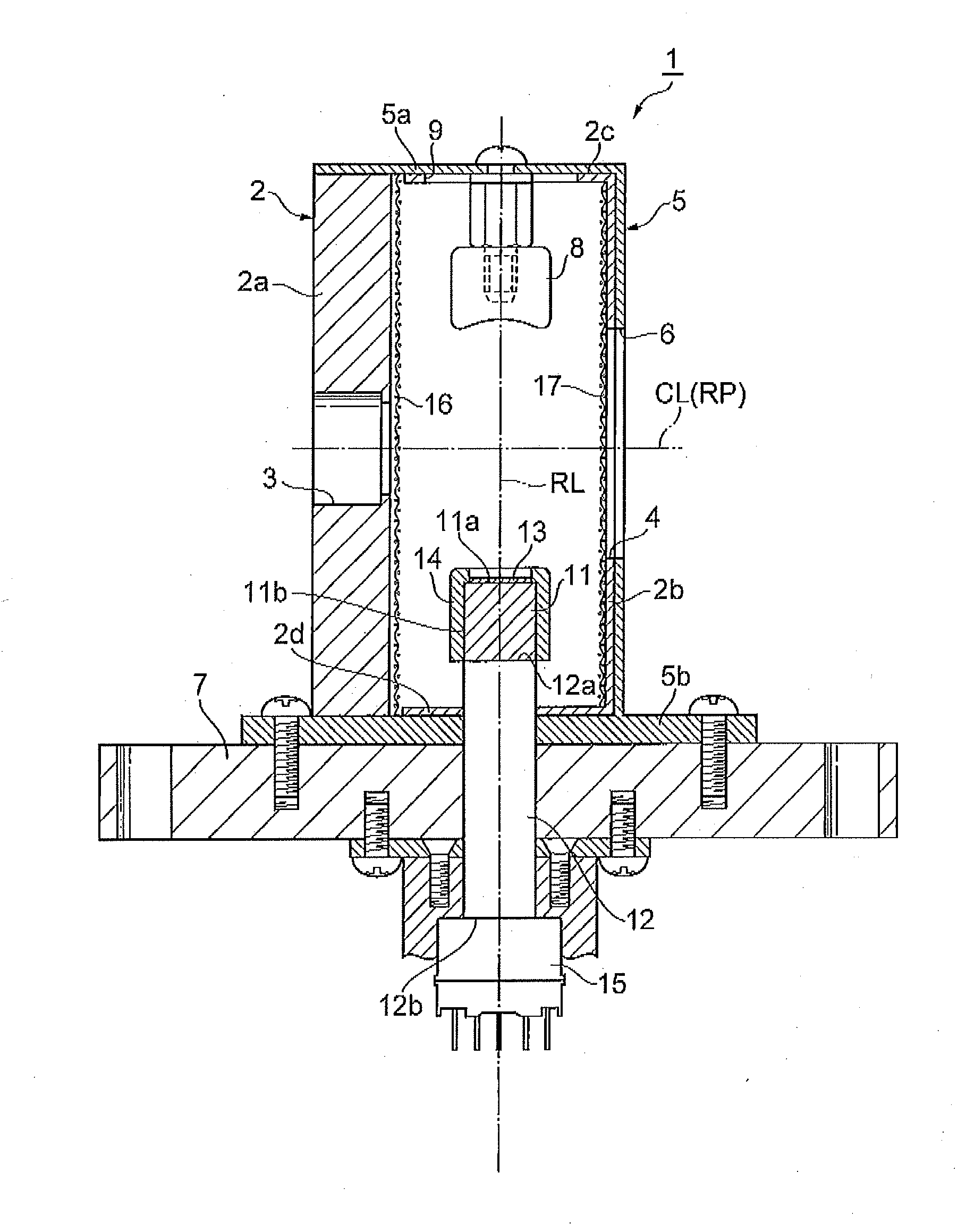
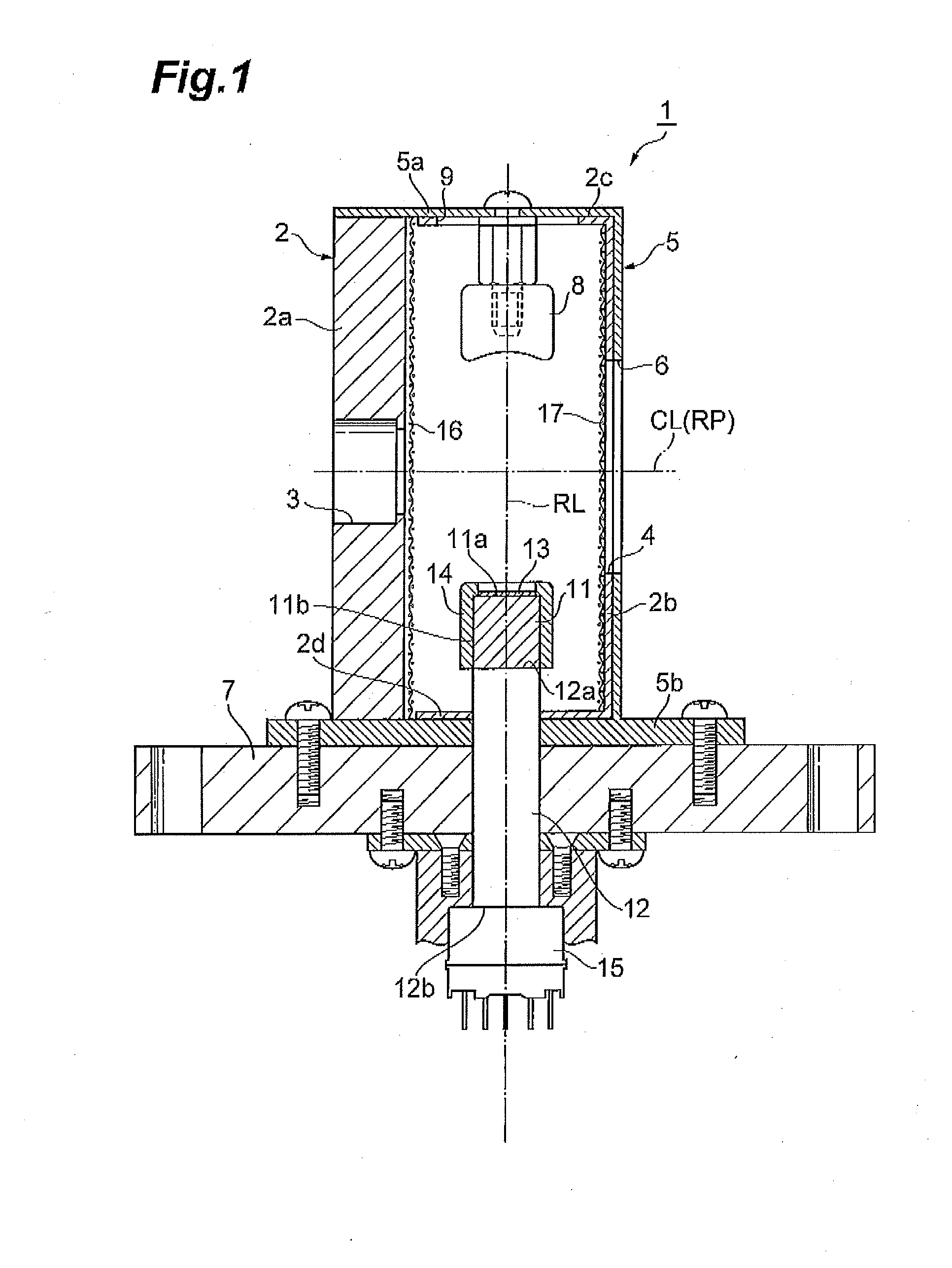
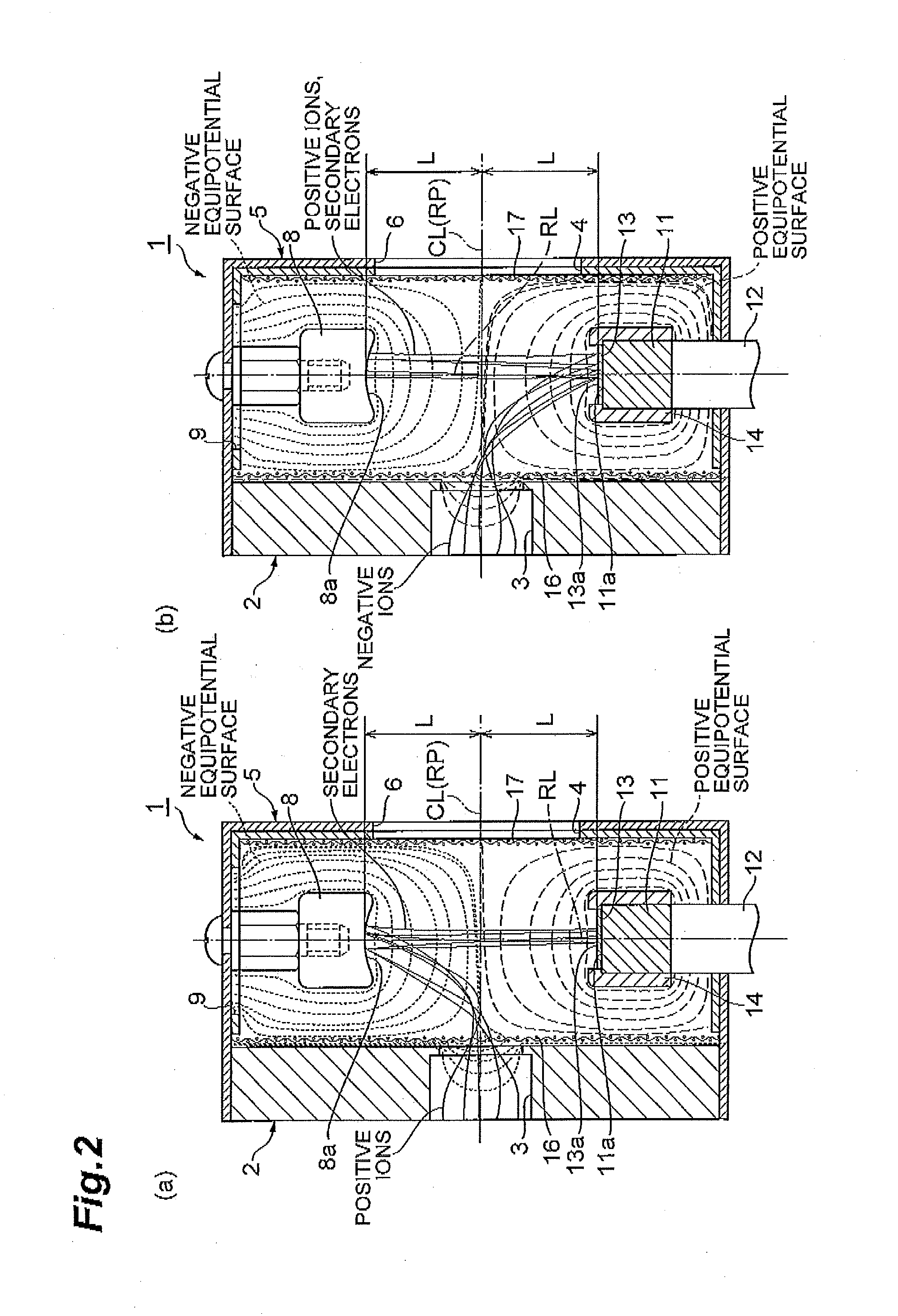
[0032]As shown in FIG. 1, an ion detector 1 includes a rectangular parallelepiped box-shaped chamber (housing) 2 made of SUS (stainless steel). In a side wall 2a of the chamber 2, an ion entrance 3 having a circular shape in section to let positive ions and negative ions enter are provided. In a side wall 2b of the chamber 2 opposed to the side wall 2a, an opening 4 opposed to the ion entrance 3 is provided. An outer surface of the chamber 2 excluding the side wall 2a is covered with an insulating member 5 made of a PEEK (polyether ether ketone) resin. In the insulating member 5, an opening 6 is provided so as to overlap with the opening 4 of the chamber 2. A bottom wall 5b of the insulating member 5 is formed like an outward flange. To the bottom wall 5b, a mounting plate 7 to mount the ion detector 1 at a predetermined position in, for example, a device (in a mass spectrometer or the like) that is vacuumed is fixed by a screw or the like.
[0033]In the chamber 2, a column-shaped con...
second embodiment
[0055]As shown in FIG. 8 and FIG. 9, an ion detector 10 is different from the foregoing ion detector 1 mainly in that a pair of electrode members 18 for converging trajectories of positive ions and negative ions that enter into the chamber 2 via the ion entrance 3 are disposed in the chamber 2.
[0056]The pair of electrode members 18 are located downstream of the mesh 16 and upstream of the dynode 8 and the conductive layer 13 (here, immediately behind the mesh 16) in the traveling direction of positive ions and negative ions that enter into the chamber 2 via the ion entrance 3. That is, the pair of electrode members 18 are located closer to the ion entrance 3 side than the dynode 8 and the conductive layer 13. Further, the pair of electrode members 18, when viewed from the ion entrance 3 side, face each other across the ion entrance 3 in a direction substantially perpendicular to the direction in which the dynode 8 and the conductive layer 13 are opposed (that is, a direction substan...
third embodiment
[0063]As shown in FIG. 12, an ion detector 20 is different from the foregoing ion detector 1 mainly in that a mesh (second mesh) 19 is placed at the ion entrance 3.
[0064]The mesh 19 is made of SUS, and is woven outside of the ion entrance 3 so as to extend along an outer surface of the side wall 2a of the chamber 2. That is, the mesh 19 is located at an outer side than the mesh 16. To the mesh 19, a positive potential and a negative potential are selectively applied so as to have an absolute value smaller than that of a potential to be applied to the mesh 16 and so as to have a polarity opposite to that of a potential to be applied to the mesh 16. For example, positive ions are detected, a negative potential of −300V is applied to the inner mesh 16, and a positive potential of +20V is applied to the outer mesh 19. On the other hand, when negative ions are detected, a positive potential of +300V is applied to the inner mesh 16, and a negative potential of −20V is applied to the outer...
PUM
 Abstract
Description
Claims
Application Information
 - R&D
- Intellectual Property
- Life Sciences
- Materials
- Tech Scout
- Unparalleled Data Quality
- Higher Quality Content
- 60% Fewer Hallucinations
Browse by: Latest US Patents, China's latest patents, Technical Efficacy Thesaurus, Application Domain, Technology Topic, Popular Technical Reports.
© 2025 PatSnap. All rights reserved.Legal|Privacy policy|Modern Slavery Act Transparency Statement|Sitemap|About US| Contact US: help@patsnap.com


