Organic electroluminescent display device

a display device and electroluminescent technology, applied in the direction of discharge tube luminescnet screens, discharge tube/lamp details, electric discharge lamps, etc., can solve the problems of high cost required for manufacturing color filters, display filters are not suitable, and the display filter is not suitable, so as to reduce the reflectance of external light, improve contrast, and improve contrast

Active Publication Date: 2012-02-02
JOLED INC
View PDF2 Cites 32 Cited by
  • Summary
  • Abstract
  • Description
  • Claims
  • Application Information

AI Technical Summary

Benefits of technology

[0024]The second light-adjusting layer secures chromatic purity of green and red by absorbing light with wavelengths between green and red. The second light-adjusting layer also absorbs external light belonging to the intermediate wavelength (for example, the peak wavelength of the fluorescent light), suppressing the reflectance of the external light and thereby improving the contrast. The first portion of the first light-adjusting layer also contributes to the increase in the contrast by absorbing the external light.
[0025]The first portion of the first light-adjusting layer also functions as the color filter for blue, securing the chromatic purity of blue. The second light-adjusting layer selectively absorbs the light with wavelength betw

Problems solved by technology

While this allows obtaining high chromatic purity, there is a problem in manufacturing cost.
As a result, high cost necessary for manufacturing color filters is unavoidable.
However, there is a problem that the display filter is not suitable for an organic EL display device having close peak wavelengths of blue light and green light.
Absorbing light at the wavelength intermediate between blue and green light in the organic EL display device absorbs light at a useful wavelength, and causes a problem such as a significant reduction in light-emitting efficiency of green at the price of chromatic purity of blue.
In this case, t

Method used


Image

  • Organic electroluminescent display device
  • Organic electroluminescent display device
  • Organic electroluminescent display device

Examples


example 1

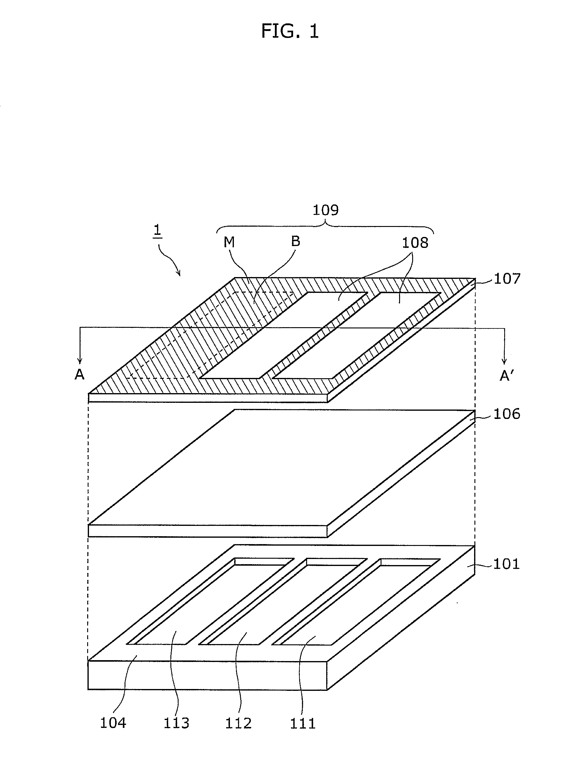
[0046]FIG. 1 is an exploded perspective view illustrating an example of the configuration of the organic EL display device 1 according to Example 1 of the present invention.

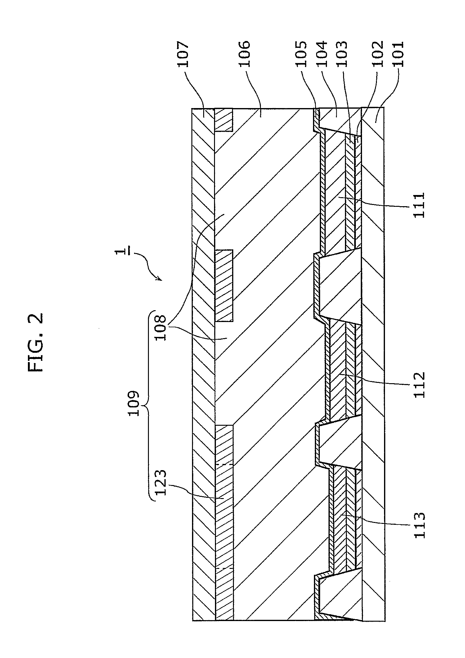
[0047]FIG. 2 is a cross-sectional view illustrating A-A′ cross-section of the organic EL display device 1.

[0048]The organic EL display device 1 is configured by bonding a main substrate 101 and a sub substrate 107 using a second light-adjusting layer 106. The main substrate 101 includes a red-light emitting layer 111, a green-light emitting layer 112, and a blue-light emitting layer 113, which are light-emitting regions for red light, green light, and blue light, respectively, and a bank 104 which is a non-light emitting region. A first light-adjusting layer 109 is formed on the sub substrate 107.

[0049]The first light-adjusting layer 109 includes a first portion (illustrated as a sign B in FIG. 1) arranged to cover the blue light-emitting layer 113, which is capable of selectively transmitting desired blue light,...

example 2

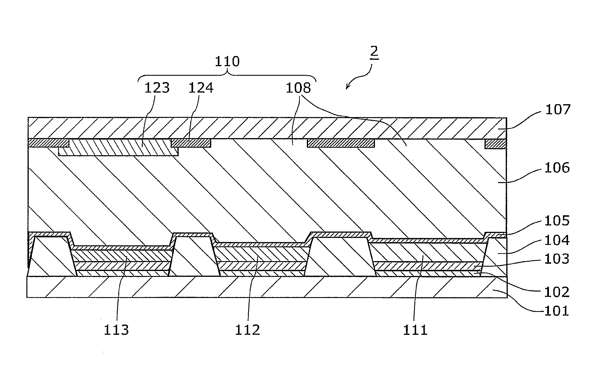
[0068]In Example 2, compared with Example 1, the method of forming the organic EL luminescent region is identical, but the configuration of the first light-adjusting layer 110 is different.

[0069]FIG. 3 is a cross-sectional view illustrating an example of configuration of the organic EL display device 2 according to Example 2, and corresponds to the A-A′ cross section of the organic EL display device 1 in FIG. 2. The first light-adjusting layer 110 in the organic EL display device 2 is manufactured as follows.

[0070]Independent from the process for manufacturing the organic EL light-emitting region on the main substrate 101, the sub substrate 107 having the first light-adjusting layer 110 is manufactured. The sub substrate 107 is, for example, a glass substrate.

[0071]The first light-adjusting layer 110 includes the blue color filter 123 positioned with the blue-light emitting layer 113, and is the first portion that selectively transmits the desired blue light, and the black matrix 12...


PUM


Abstract

An organic EL display device including organic EL light-emitting regions which includes a red-light emitting layer, a green-light emitting layer, and a blue-light emitting layer that are arranged on a main substrate includes: a first light-adjusting layer including a first portion and a second portion, the first portion selectively transmitting desired blue light, and the second portion absorbing visible light other than at least the desired blue light; and a second light-adjusting layer selectively absorbing light with a wavelength between desired red light and desired green light at an entire surface, in which the blue light-emitting layer is overlaid with the first portion, and a bank which is a non-light emitting portion is overlaid with the second portion. The first portion and the second portion may be integrally formed of a same material, and the second portion may absorb an entire range of visible light.

Description

CROSS REFERENCE TO RELATED APPLICATION[0001]This is a continuation application of PCT application No. PCT / JP2010 / 002502 filed on Apr. 6, 2010, designating the United States of America.BACKGROUND OF THE INVENTION[0002](1) Field of the Invention[0003]The present invention relates to an organic electroluminescent (EL) display device capable of emitting light in multiple colors.[0004](2) Description of the Related Art[0005]An organic EL display device is a light-emitting display device utilizing electroluminescence of organic compound, and has been in practical use as a small display device used for mobile phones, for example.[0006]The organic EL display device includes organic EL elements arranged on a substrate, and each of the organic EL display elements of a pixel can be individually controlled for light emission. The organic EL display device capable of emitting light in multiple colors includes single-color light-emitting organic EL elements each emits light in different colors (d...

Claims


Application Information

Patent Timeline
IPC IPC(8): H01L27/32
CPCH01L27/3211H01L51/5284H01L27/322H10K59/35H10K59/38H10K50/865H10K50/125
Inventor OKUMOTO, KENJIMATSUI, MASAFUMIOHTA, TAKASHIKORESAWA, KOUHEI
Owner JOLED INC
Why Eureka
Try Eureka