Method of charging battery and battery charging control system

a control system and battery technology, applied in electric vehicles, transportation and packaging, electric power, etc., can solve the problems of shortened battery life, battery electrode damage before the battery voltage reaches the upper limit, and the charging method using external heating is undesirable in the consideration of vehicle layout, etc., to avoid deterioration of the battery

Inactive Publication Date: 2012-02-02
EC POWER LLC +1
View PDF1 Cites 41 Cited by
  • Summary
  • Abstract
  • Description
  • Claims
  • Application Information

AI Technical Summary

Benefits of technology

[0026]According to the method, because the controller 3 obtains the estimation value of the ion concentration by the difference equation including the ion concentration of the active material at the electrode portion, the controller 3 can estimate the ion concentration by a simple calculation. Because the controller 3 can estimate the ion concentration of the active material at the surface of the electrode with the difference equation, the controller 3 can obtain the estimation value of the ion concentration with avoiding deterioration of the battery can be obtained.
[0027]According to the present invention, when the battery at a low temperature is heated by the pulse charging and discharging, a mode is switched between charging and discharging before an ion concentration, being a factor regarding deterioration of the battery, exceeds a threshold. Therefore, the charging mode can be moved to the normal charging mode after heating to a desired temperature of the battery without deterioration of the battery.

Problems solved by technology

Because quick charging may result in deterioration and shortened life time of the battery, it is recommended to charge the battery with a charging current corresponding to one-tenth of a rated capacity (0.1 C) for about ten hours from the viewpoint of protection of the battery.
Such a charging method using external heating is undesirable in consideration of layout in the vehicle because an external heating device should be mounted on the vehicle and an additional power source for a heater becomes necessary.
Actually, electrodes of the battery may be damaged before the battery voltage reaches the upper limit by causes such as deposition of lithium (Li) on a negative electrode of the lithium base battery.
This operation results in poor usability for charging the battery.

Method used


Image

  • Method of charging battery and battery charging control system
  • Method of charging battery and battery charging control system
  • Method of charging battery and battery charging control system

Examples


embodiment

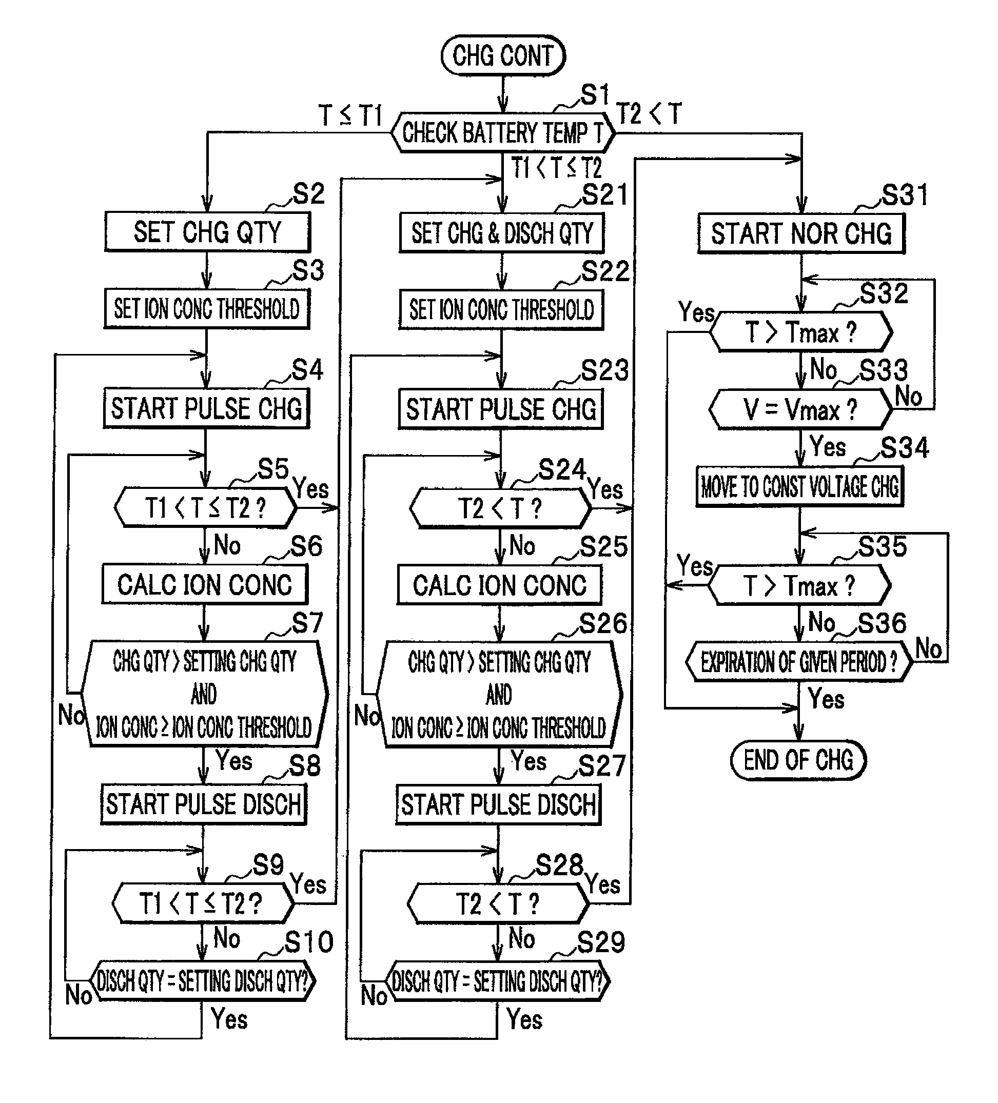
[0042]In the method of charging the battery of an embodiment, an ion concentration at a surface of an active material of an electrode is considered as a factor relating to damage of the electrode, and thus pulse widths are determined on the basis of an ion concentration at a surface of electrodes real-timely estimated. This enables the charging and discharging control with an appropriate heating of the battery without damage to the electrodes during heating the battery by the pulse charging and discharging. Hereinbelow will be described the method of charging the battery in a case where a lithium base battery is exemplified.

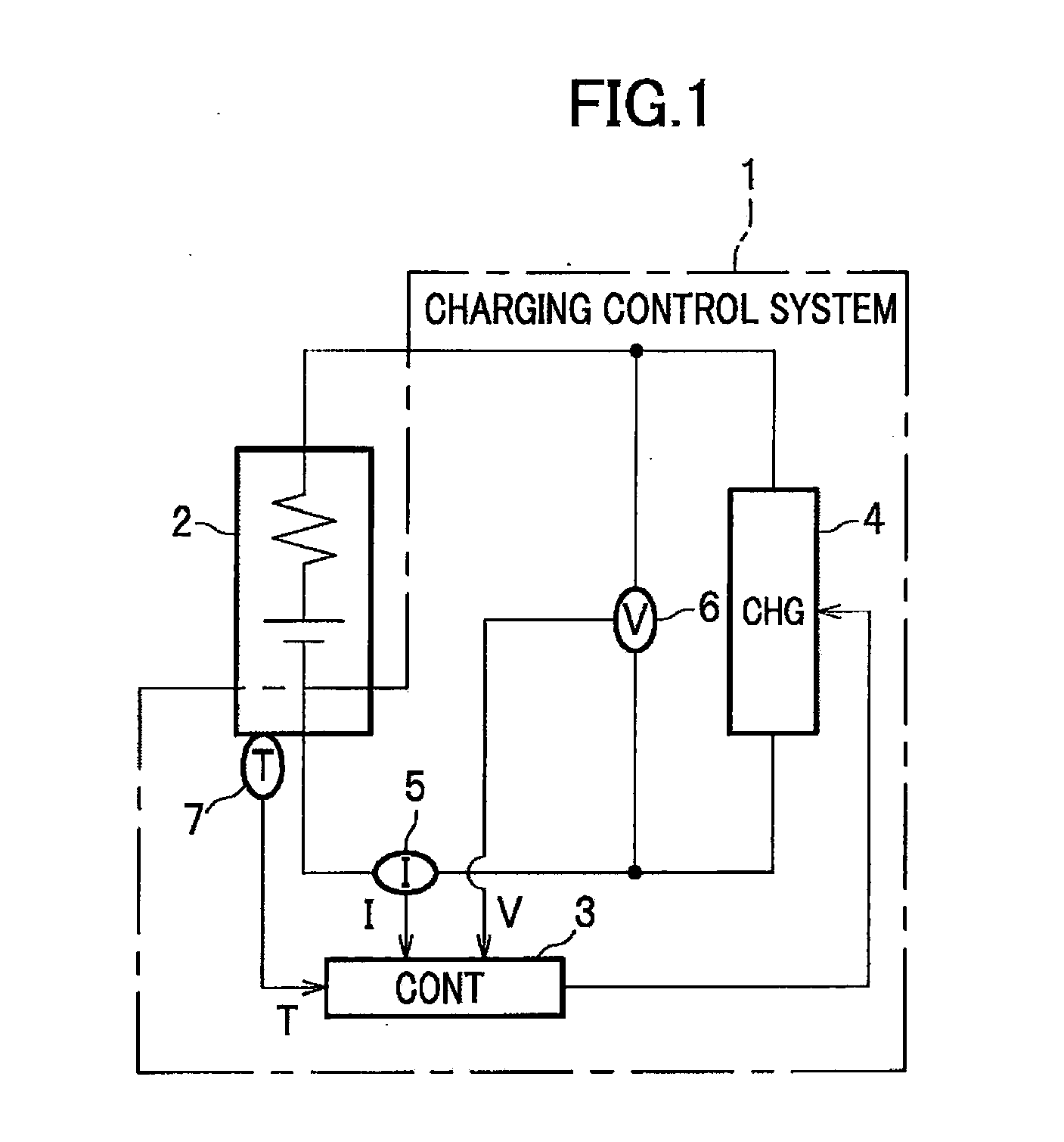
[0043]FIG. 1 is a circuit diagram of a battery charging control system configured to perform the method of charging a battery according to the embodiment of the present invention. The charging control system 1 shown in FIG. 1, mounted on, for example, a hybrid vehicle and an electric vehicle, is used to charge a battery 2 for supplying an electric power to a load...


PUM


Abstract

A controller in a charging control system controls a charger to heat a battery at a low temperature by pulse charging and discharging up to a desired temperature and then moves to a normal charging mode. The controller calculates an ion concentration of an active material at electrode portions of the battery on the basis of the temperature data and the electric current data obtained, switch the pulse charging and discharging between a charging mode and a discharging mode on the basis of a pulse width when the ion concentration reaches a threshold.

Description

BACKGROUND OF THE INVENTION[0001]1. Field of the Invention[0002]The present invention relates to a method of charging a battery and a battery charging control system, and particularly to a method of charging a battery such as a lithium ion battery at a low temperature for fast charging and a battery charging control system for fast charging.[0003]2. Description of the Related Art[0004]Vehicles such as hybrid electric vehicles (HEV) and electric vehicles (EV) travel by driving a motor using electric power from a battery. When a remaining charge in the battery decreases by discharging during, for example, traveling and a long period parking, the battery should be charged. Because quick charging may result in deterioration and shortened life time of the battery, it is recommended to charge the battery with a charging current corresponding to one-tenth of a rated capacity (0.1 C) for about ten hours from the viewpoint of protection of the battery. Since the battery at a low temperature ...

Claims


Application Information

Patent Timeline
Patent Type & Authority Applications(United States)
IPC IPC(8): H02J7/00
CPCH02J7/047H02J7/045
Inventor WANG, CHAO-YANGKWON, OU JUNGISHIKAWA, YOSUKE
Owner EC POWER LLC
Why Eureka
Try Eureka