Coil

a coil and diametrical direction technology, applied in the field of coils, can solve the problems of increasing the size of the transmitter, the inability to realize the effect of efficient power transmission with respect to a receiver having a coil of a different diameter, and the need for a larger space in the direction of the winding shaft axis, so as to achieve the effect of reducing the thickness, reducing the diametrical direction of one coil, and reducing the thickness

Active Publication Date: 2012-02-02
SUMIDA CORP
View PDF5 Cites 7 Cited by
  • Summary
  • Abstract
  • Description
  • Claims
  • Application Information

AI Technical Summary

Benefits of technology

[0024]Since the coil in accordance with the present invention includes a first winding wound about a winding shaft axis and a second winding wound coaxially on the outer circumferential portion of the first winding, it is possible to switch between a mode in which only the first winding is used as a small-diameter coil and a mode in which the first winding and the second winding are used together as one large-diameter coil, that is, to change the diameter of the region used as a coil. Furthermore, since the second winding is wound so as to be in intimate contact with the outer circumferential side of the first winding, no unnecessary space appears between the first winding and the second winding, and therefore, the size in the diametrical direction of one coil can be reduced.
[0025]Further, at least in the first winding among the two windings, one side of the winding wire is wound from the inner circumferential side to the outer circumferential side, the other side of the winding wire is drawn forth from the inner circumferential side to the outer circumferential side, while crossing the one side of the winding wire, and the thickness in the crossing portions of the one side of the winding wire and the other side of the winding wire in the direction of the winding shaft axis is equal to the thickness in other portions. Therefore, at least in the winding region of the first winding, the thickness of the drawing line portion of the other side of the winding wire does not become larger than the thickness of other portions and therefore uniformity of thickness in the direction of the winding shaft axis can be achieved and thickness can be reduced.
[0026]Further, if a configuration is used in which in both the first winding and the second winding, the ...

Problems solved by technology

Therefore, efficient power transmission is difficult to realize with respect to a receiver having a coil of a different diameter.
However, the problem is that since a space should be ensured to accommodate a plurality of coils side by side, the transmitter is increased in size.
However, the problem is that because the coils should be pil...

Method used


Image

  • Coil
  • Coil
  • Coil

Examples


first embodiment

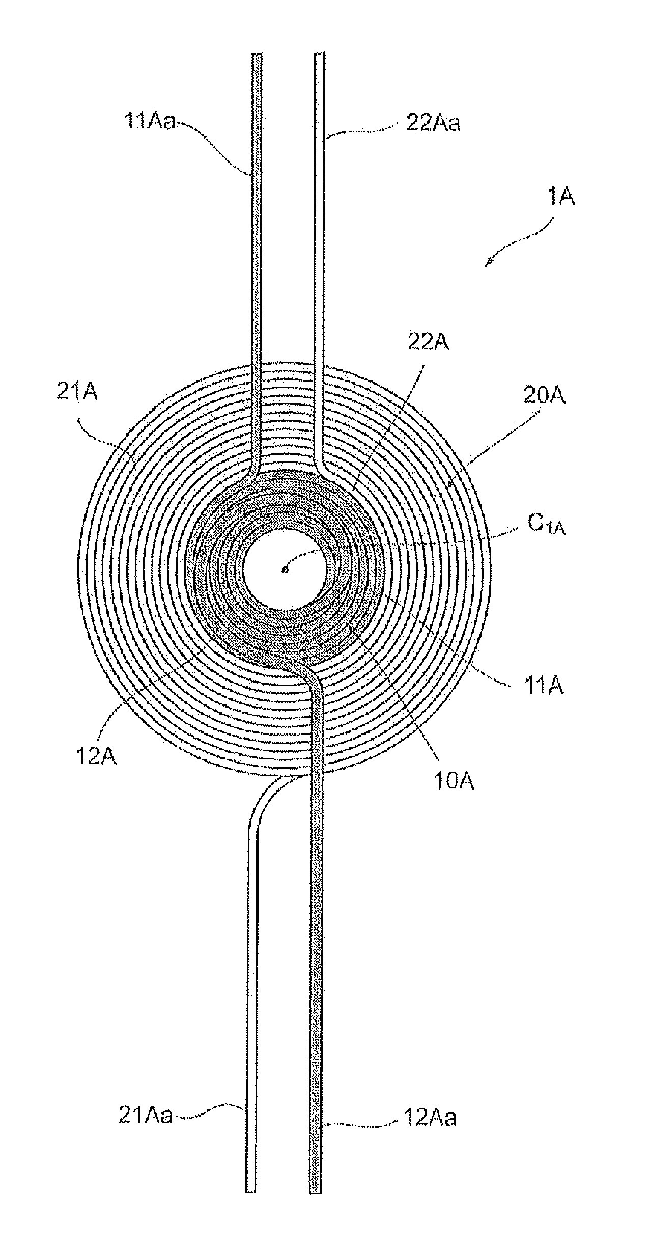
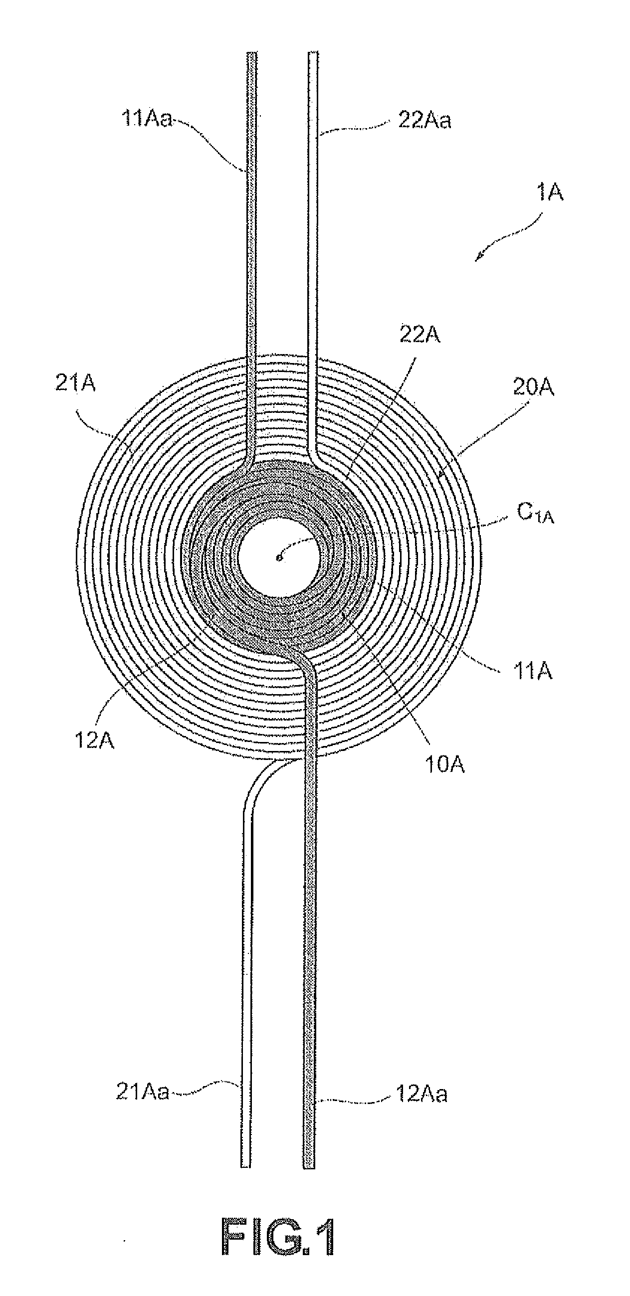
[0041]A coil 1A according to the first embodiment shown in FIG. 1 is a thin-type air-core coil (the air-core portion is round) that can be advantageously used for contactless power transmission. The coil includes a first winding 10A (in the present embodiment, this winding is constituted by a plurality of wires) wound about a winding shaft axis C1A (virtual line perpendicular to the sheet surface) and a second winding 20A (in the present embodiment, this winding is constituted by a plurality of wires) wound coaxially with the first winding 10A so as to be in intimate contact with the outer circumferential portion of the first winding 10A.

[0042]In the first winding 10A and the second winding 20A, each wire of the plurality of wires constituting the windings is the so-called self-fusing wire (for example, a polyurethane-coated copper wire covered on the outer side with a thermoplastic fusible varnish or the like). At the stage of winding with a winding machine (not shown in the figure...

second embodiment

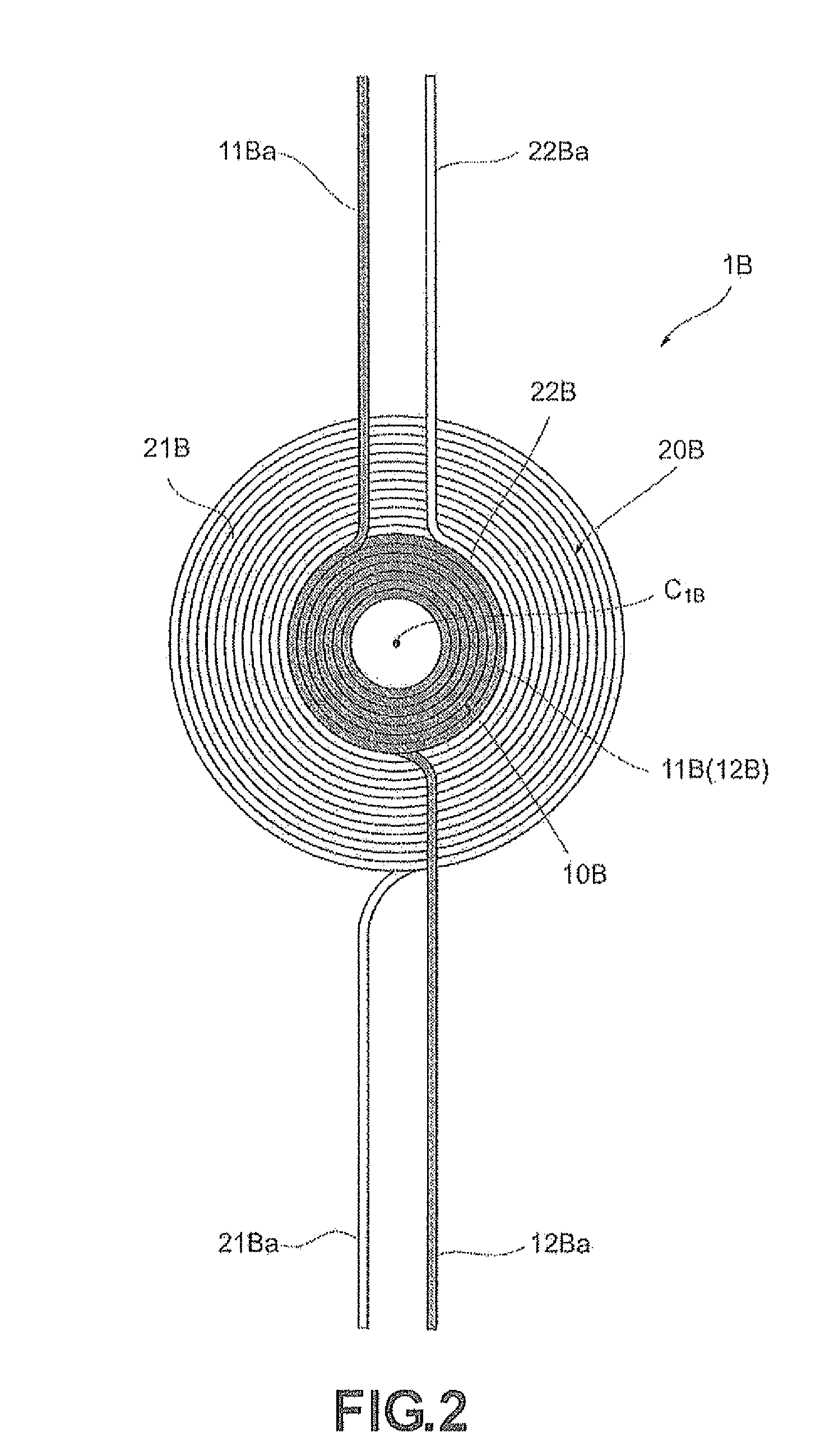
[0060]Similarly to the above-described coil 1A of the first embodiment, a coil 1B of the second embodiment illustrated by FIG. 2 is also a thin-type air-core coil that can be advantageously used for contactless power transmission and includes a first winding 10B (in the present embodiment, this winding is constituted by a plurality of wires) wound about the winding shaft axis C1B and a second winding 20B (in the present embodiment, this winding is constituted by a plurality of wires) wound coaxially with the first winding 10B so as to be in intimate contact with the outer circumferential portion of the first winding 10B.

[0061]The above-mentioned first winding 1013 is wound by the cc winding method. Thus, one side 11B of the winding wire is tightly wound in the clockwise direction, as shown in the FIG. 2, from the inner circumferential side to the outer circumferential side of the first winding 10B, and the other side 1211 of the winding wire is tightly wound (at the same angular spe...

third embodiment

[0064]Similarly to the above-described coil 1A of the first embodiment and coil 1B of the second embodiment, a coil 1C of the third embodiment illustrated by FIG. 3 is also a thin-type air-core coil that can be advantageously used for contactless power transmission and includes a first winding 10C (in the present embodiment, this winding is constituted by a plurality of wires) wound about the winding shaft axis C1C and a second winding 20C (in the present embodiment, this winding is constituted by a plurality of wires) wound coaxially with the first winding 10C so as to be in intimate contact with the outer circumferential portion of the first winding 10C.

[0065]The first winding 10C is wound by the naruto spiral winding method. Thus, one side 11C of the winding wire is tightly wound in the clockwise direction, as shown in the FIG. 3, from the inner circumferential side to the outer circumferential side of the first winding 10C, and the other side 12C of the winding wire is drawn for...


PUM


Abstract

A coil is formed by coaxially winding a second winding so as to be in intimate contact with an outer circumferential portion of a first winding wound about a winding shaft axis. In the first winding, one side of a winding wire is wound from an inner circumferential side to an outer circumferential side, the other side of the winding wire is drawn forth from the inner circumferential side to the outer circumferential side, while crossing the one side of the winding wire, and a thickness in a direction of the winding shaft axis in crossing portions of the one side of the winding wire and the other side of the winding wire is equal to a thickness in other portions.

Description

RELATED APPLICATIONS[0001]This application claims the priority of Japanese Patent Application No. 2010-172477 filed on Jul. 30, 2010 which is incorporated herein by reference.BACKGROUND OF THE INVENTION[0002]1. Field of the Invention[0003]The present invention relates to a coil to be used suitable as an inductor or transformer for various electric devices, and more particularly to a thin-type coil advantageously suitable for contactless power transmission (contact-free power transmission).[0004]2. Description of the Related Art[0005]The technology of contactless power transmission designed so that power exchange is performed in a contactless (contact-free) manner by electromagnetic coupling of a coil in a transmitter and a coil in a receiver has found use in cellular phones, portable information terminal devices, and home electric devices (see Japanese Laid-Open Patent Publication No. 2008-172872 and Japanese Laid-Open Patent Publication No. 2005-6440 below).[0006]In a large number ...

Claims


Application Information

Patent Timeline
IPC IPC(8): H01F27/28H01F38/14
CPCH01F38/14H01F27/2871H01F27/2828
Inventor KIKUCHI, SHUICHIKURODA, MORIHIRO
Owner SUMIDA CORP
Why Eureka
Try Eureka