Line image forming method and apparatus

a line image and forming method technology, applied in the direction of typewriters, duplicating/marking methods, printing, etc., can solve the problems of dots being grouped, and achieve the effect of preventing the image from being formed, good linearity, and satisfactory line shap

Active Publication Date: 2012-02-02
FUJIFILM CORP
View PDF6 Cites 6 Cited by
  • Summary
  • Abstract
  • Description
  • Claims
  • Application Information

AI Technical Summary

Benefits of technology

[0031]According to this aspect of the present invention, it is possible to irradiate activating light immediately after image formation by the inkjet head. Furthermore, since laser light has good linearity and light is not liable to enter into the nozzles of the inkjet head, then it is desirable to irradiate laser light from the activating light irradiation device in a mode where the activating light irradiation device is arranged in close proximity to the inkjet head.
[0032]According to the present invention, it is possible to prevent the image formed as a line pattern from assuming a plurality of dot shapes, and a satisfactory line shape can be formed.

Problems solved by technology

Consequently, when image formation is carried out as described in Japanese Patent Application Publication No. 2008-294308, a satisfactory line shape is not obtained under certain conditions, resulting in a plurality of dots.

Method used


Image

  • Line image forming method and apparatus
  • Line image forming method and apparatus
  • Line image forming method and apparatus

Examples


first embodiment

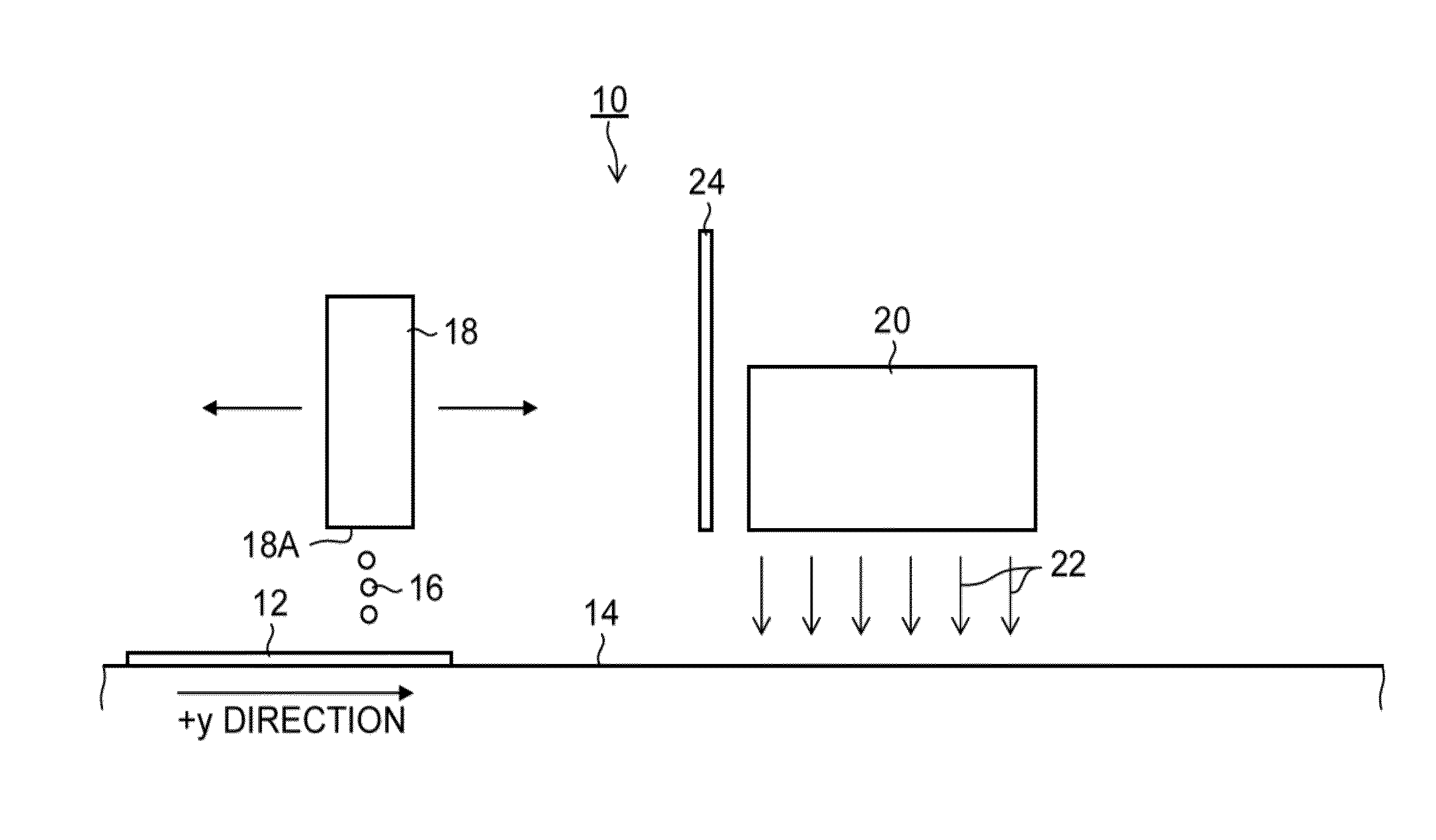
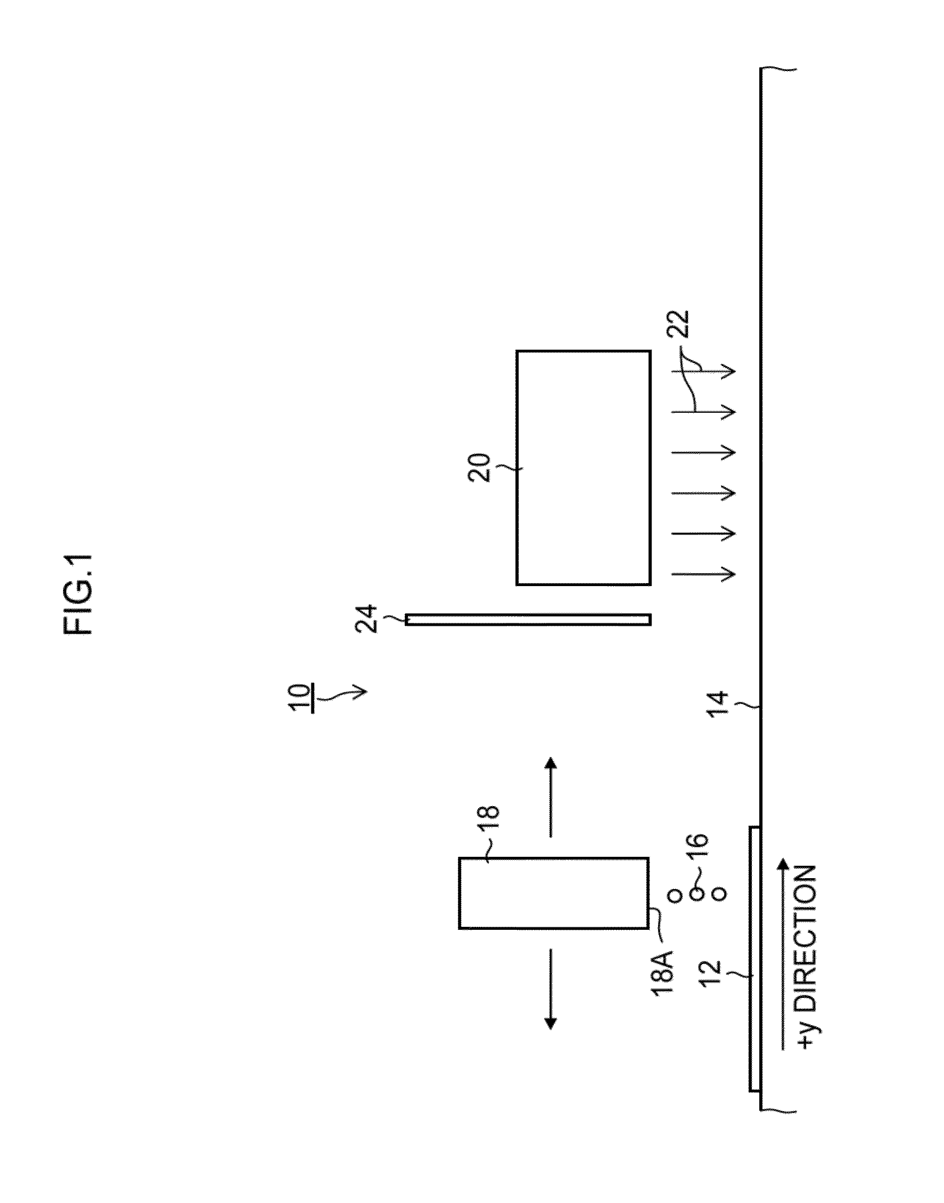
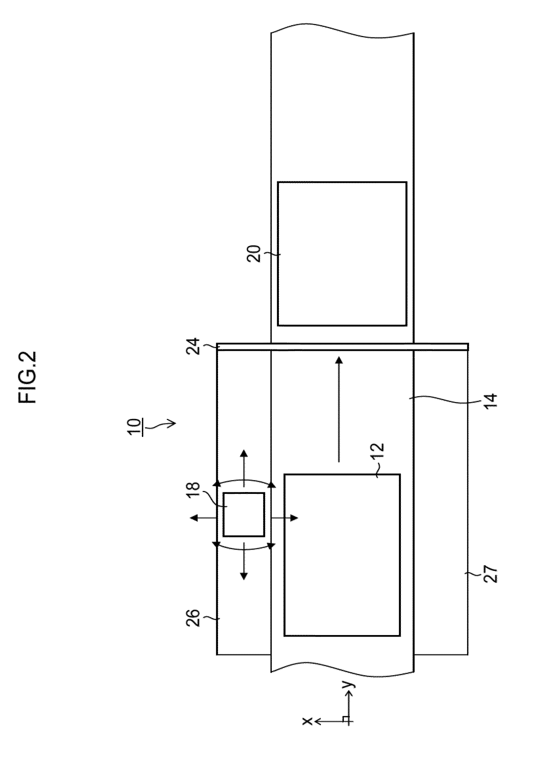
[0056]FIG. 1 is a side view of a line image forming apparatus according to a first embodiment of the present invention, and FIG. 2 is a plan view of same. As shown in FIGS. 1 and 2, the line image forming apparatus 10 in the present embodiment includes: a belt 14 (corresponding to a “movement device” and a “medium conveyance device”), which conveys a substrate 12 (corresponding to a “non-permeable medium”); an inkjet head 18 (hereinafter referred to as “recording head”), which ejects a functional liquid 16 (here, a liquid having an action of being cured by ultraviolet light, called “UV ink” for the sake of convenience) toward the substrate 12, and a UV light irradiation device 20 (corresponding to an “activating light irradiation device”).

[0057]The substrate 12 is an image formation medium on which the UV ink 16 ejected from the recording head 18 is deposited. For the substrate 12, a non-permeable medium (e.g., made of resin), or a low-permeability medium having a sufficiently long ...

second embodiment

[0140]FIG. 19 is a diagram showing a side view of a line image forming apparatus 110 according to a second embodiment of the present invention, and FIG. 20 is a plan view of same. In FIGS. 19 and 20, elements which are the same as or similar to the composition described with reference to FIGS. 1 and 2 are denoted with the same reference numerals, and description thereof is omitted here.

[0141]The line image forming apparatus 110 according to the second embodiment shown in FIGS. 19 and 20 employs a supporting plate 114 as a conveyance device for the substrate 12. The supporting plate 114 is able to move in the x direction and the y direction which is perpendicular to the x direction, by means of a movement mechanism (for example, an xy table, or the like), which is not illustrated. It is also possible to arrange a mechanism for turning the supporting plate 114 in the xy plane.

[0142]Furthermore, a UV laser irradiation device 120 is attached to the recording head 18. The recording head ...

third embodiment

Use of Ink Containing Volatile Solvent

[0158]In the third embodiment described below, a liquid produced by mixing a functional component (for example, metal nano-particles) with a volatile solvent (for example, water or tetradecane) is used, and an image of a line pattern is formed on the substrate by performing a relative scanning action of a recording head with respect to a substrate. For the apparatus composition, it is possible to employ a composition similar to the first embodiment described with reference to FIG. 1, and the like, and the second embodiment described with reference to FIG. 19, and the like. Furthermore, it is possible to adopt a mode omitting the UV light irradiation device 20 from the first embodiment in FIG. 1, or the like, or a mode omitting the UV laser irradiation device 120 from the second embodiment in FIG. 19, or the like.

[0159]In the third embodiment, the conditions including the receding contact angle condition (not larger than 10°) described in relatio...


PUM

PropertyMeasurementUnit
contact angleaaaaaaaaaa
ejection frequencyaaaaaaaaaa
static contact angleaaaaaaaaaa

Abstract

A line image forming method includes the steps of: ejecting a plurality of droplets of liquid sequentially from an inkjet head, the liquid containing a functional component; and depositing the droplets of the liquid onto a non-permeable medium, the deposited droplets becoming joined together on the non-permeable medium to form a line pattern of the liquid, wherein a receding contact angle of the liquid with respect to the non-permeable medium being not larger than 10°.

Description

BACKGROUND OF THE INVENTION[0001]1. Field of the Invention[0002]The present invention relates to a line image forming method and a line image forming apparatus, and more particularly to line image formation technology suitable for forming a line pattern on a surface of a non-permeable medium using an inkjet head.[0003]2. Description of the Related Art[0004]Japanese Patent Application Publication No. 2008-294308 discloses technology for forming a desired conductive pattern (circuit pattern) by applying a metallic nano-ink onto a polyimide film by inkjet printing. According to Japanese Patent Application Publication No. 2008-294308, by making the contact angle of the metallic nano-ink with respect to the polyimide film 10° or greater, bleeding of the metallic nano-ink after application is suppressed, and improvement in the accuracy of the pattern dimensions is achieved.[0005]In Japanese Patent Application Publication No. 2008-294308, a metallic nano-ink droplet is dripped onto a polyi...

Claims


Application Information

Patent Timeline
Patent Type & Authority Applications(United States)
IPC IPC(8): B41J29/38B41J2/04
CPCB41J2/2107B41J3/407B41M5/0047B41J29/393B41J11/002B41J11/00214
Inventor MATAKI, HIROSHI
Owner FUJIFILM CORP
Why Eureka
Try Eureka