Stereo image processor and stereo image processing method

a stereo image and image processing technology, applied in image enhancement, image analysis, instruments, etc., can solve the problems of small camera spacing, low accuracy of sub-pixel level disparity calculation, and small partial displacement between stereo images, so as to improve the accuracy of disparity calculation and analytical resolution, the effect of less computation and fast processing

Inactive Publication Date: 2012-02-02
PANASONIC INTELLECTUAL PROPERTY MANAGEMENT CO LTD
View PDF1 Cites 29 Cited by
  • Summary
  • Abstract
  • Description
  • Claims
  • Application Information

AI Technical Summary

Benefits of technology

[0011]The present invention has been made under such circumstances. It is an object of the invention to provide a stereo image processor that has improved

Problems solved by technology

However, the smaller size of recent cameras, such as on-board and inboard cameras, have led to a smaller camera spacing and resultant smaller partial displacement between stereo images.
However, the SAD method suffers from low accuracy of sub-pixel level disparity calculation; the SAD method can determine disparity (i.e. partial displacement between images) only on the order of ¼ to 1/16 pixel accuracy and is difficult to satisfy the need for highly accurate disparity calculating functions.
However, the 2D POC method requires a large amount of computation in disparity calculation, and it is difficult to compute in a short time.
In addition, the 2D POC method is inferior to

Method used


Image

  • Stereo image processor and stereo image processing method
  • Stereo image processor and stereo image processing method
  • Stereo image processor and stereo image processing method

Examples


embodiment 1

[0034]A stereo image processor according to embodiments of the present invention will now be described below with reference to drawings. In this embodiment, description will be made as an example to a stereo image processor for use in devices such as one that measures a distance to a vehicle in front by using an on-board camera or one that estimates the direction of the driver's face by using an inboard camera.

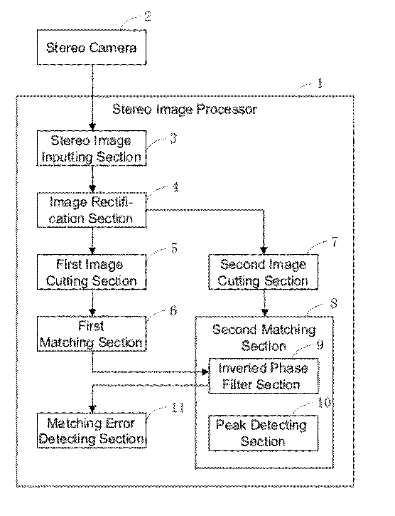
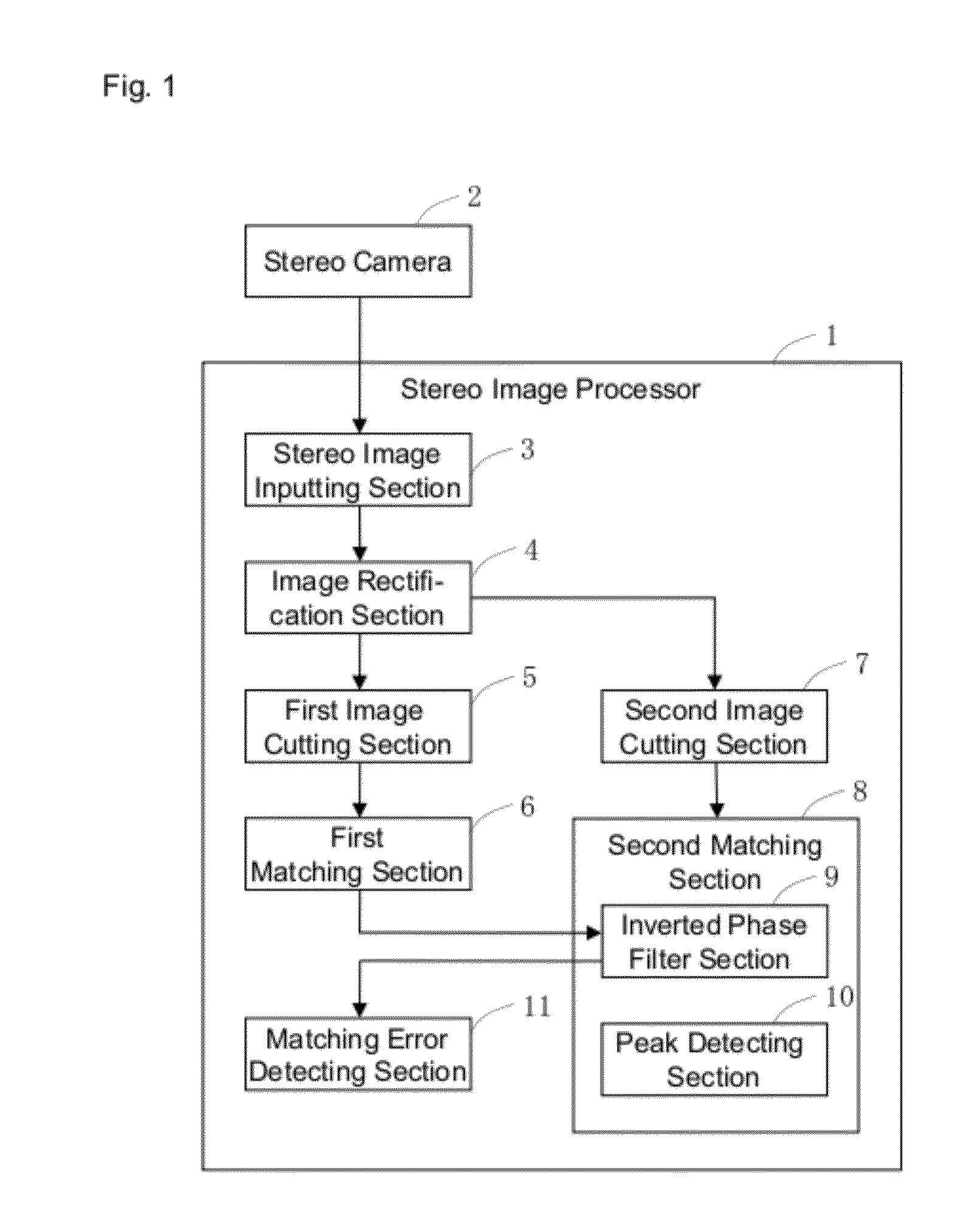
[0035]A configuration of a stereo image processor according to the embodiment will now be described below with reference to drawings. FIG. 1 is a block diagram of a configuration of a stereo image processor according to the embodiment. As shown in FIG. 1, a stereo image processor 1 comprises a stereo image inputting section 3 that receives, as an input, stereo images (a base image and a comparative image) taken by a stereo camera 2, and an image rectification section 4 for correcting lens distortion and arranging optical axes in parallel in stereo images (a base image and a co...

embodiment 2

[0075]FIG. 9 is a block diagram for illustrating a configuration of a stereo image processor 1 according to a further embodiment. As shown in FIG. 9, a second matching section 8 according to the embodiment is provided with a cross-correlation section 12, instead of the inverted phase filter section 9. The cross-correlation section 12 has a function of calculating a value of cross-correlation, given partial images at positions matched in the pixel level matching. The cross-correlation section 12, therefore, corresponds to “cross-correlation calculating means” of the invention.

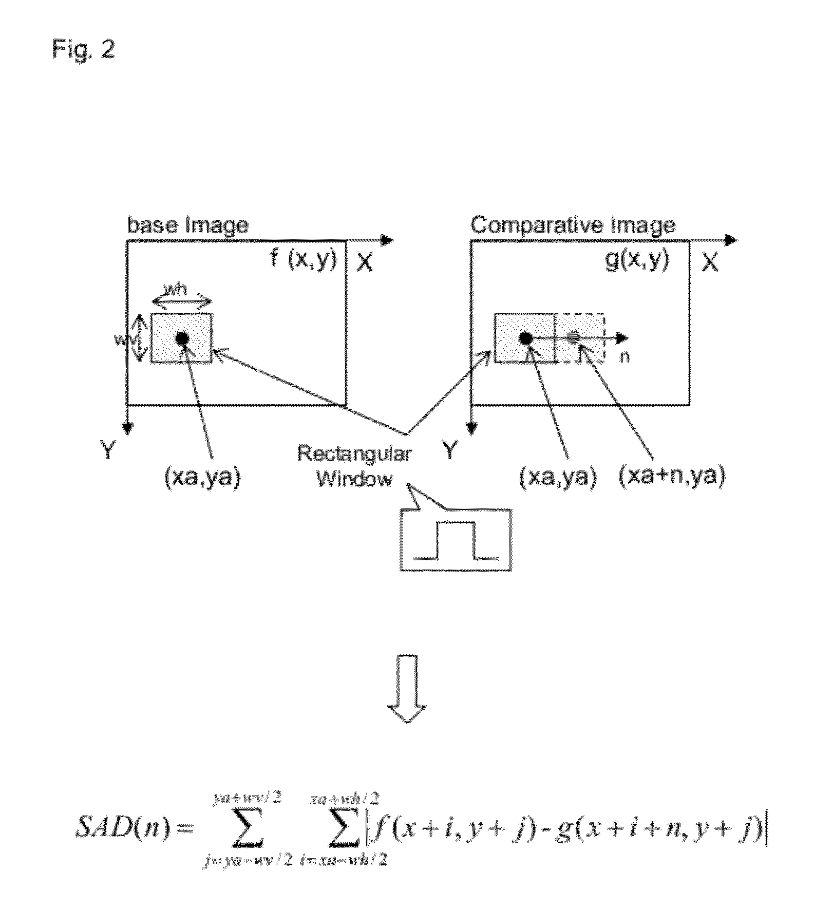
[0076]FIG. 10 is a diagram for illustrating a process of calculating a value of cross-correlation. In this case, as shown in FIG. 10, a window function w(m) of a Hanning window as shown in the expression (2) is used to cut off data from a base image with a predetermined position (xa,ya) centered, and cut off data from a comparative image with a position (xa+n,ya) centered, which has been matched in pixel level m...

embodiment 3

[0088]FIG. 13 shows a configuration of a stereo image processor 1300 according to Embodiment 3 of the invention. The stereo image processor 1300 is composed of a stereo image acquiring section 1301, an image matching section 1302, a filter section 1303, and a peak position detecting section 1304.

[0089]Here, the stereo image acquiring section 1301 corresponds to the stereo camera 2 and the stereo image inputting section 3 in FIG. 1, the image matching section 1302 corresponds to the first image cutting section 5 and the first matching section 6 in FIG. 1, the filter section 1303 corresponds to the second image cutting section 7 and the inverted phase filter section 9 in FIG. 1, and the peak detecting section 1304 corresponds to the peak detecting section 10 in FIG. 1.

[0090]Description will now be made to functions of the stereo image processor 1300 according to Embodiment 3 with reference to FIG. 13. In the description below, it is assumed that an image described below has the X axis...


PUM


Abstract

A stereo image processor (1) performs image matching, in an image matching section (6), on partial images of the same object included in a base image and a comparative image respectively and detects pixel-precision partial displacement between the base image and the comparative image based on a result of the image matching. Next, in an inverted phase filter processing section (9) in a second matching section (8), pixel values from the comparative image are filtered with an inverted phase filter using, as a filter coefficient, pixel values from the base image with the order thereof reversed, given the partial images of the same object that have minimum pixel-precision partial displacement. Then, in a peak detecting section (10), a peak position where an output value of the filtering with the inverted phase filter is maximum is detected and sub-pixel-precision partial displacement between the base image and the comparative image is detected based on the peak position. In this way, there is provided a stereo image processor that has improved accuracy of disparity calculation and analytical resolution and that requires less computation for disparity calculation and is capable of fast processing.

Description

TECHNICAL FIELD[0001]The present invention relates to a stereo image processor that calculates partial displacement between images caused by disparity based on stereo images (a base image and a comparative image) obtained by taking images of the same object.BACKGROUND ART[0002]Conventionally, a stereo image processor is known, which calculates partial displacement between images based on two images (a base image and a comparative image) obtained when a stereo camera is used to take images of the same object, and measures a distance to the object based on the partial displacement between the images. The stereo image processor is under study for application to devices such as one that measures a distance to a vehicle in front based on images obtained by using an on-board camera to take the images of the vehicle or one that measures a distance to a part of the driver's face, such as an eye and a nose, based on images obtained by using an inboard camera to take the images of the face an...

Claims


Application Information

Patent Timeline
IPC IPC(8): H04N13/02
CPCG01B11/26G01C11/06G06T7/0026G06T2207/10012H04N2013/0081G06T7/2086G06T2207/20228H04N13/0022G06T7/0044G06T7/32G06T7/74G06T7/285H04N13/128
Inventor NISHIMURA, HIROFUMINANRI, TAKUYAMARUYA, KENSUKE
Owner PANASONIC INTELLECTUAL PROPERTY MANAGEMENT CO LTD
Why Eureka
Try Eureka