Energy efficient building environmental control apparatus and method

a technology of environmental control and building construction, applied in lighting and heating apparatus, ventilation systems, heating types, etc., can solve the problems of ever increasing energy consumption concerns, and achieve the effect of improving the energy performance of the building

Inactive Publication Date: 2012-02-02
SACKS INDAL
View PDF3 Cites 25 Cited by
  • Summary
  • Abstract
  • Description
  • Claims
  • Application Information

AI Technical Summary

Benefits of technology

[0008]A building includes exterior walls that form spaces which are selectively vented under control of a control system. Vents are operated to retain trapped air or exhaust trapped air to improve the energy performance of the building. Vents with selectively operable dampers may be located proximate a top of a wall or wall section of wall. Vents may also be located proximate a bottom of a wall or wall section to allow drainage of liquid and circulation of air. Various specific wall constructions provide for an air gap between layers of exterior sheathing of the exterior wall. The air gap may be in addition to a space between interior and exterior sheathing, which space may include a thermal insulation material (e.g., fiberglass batting).

Problems solved by technology

There is ever increasing concern regarding energy consumption.

Method used


Image

  • Energy efficient building environmental control apparatus and method
  • Energy efficient building environmental control apparatus and method
  • Energy efficient building environmental control apparatus and method

Examples


examples

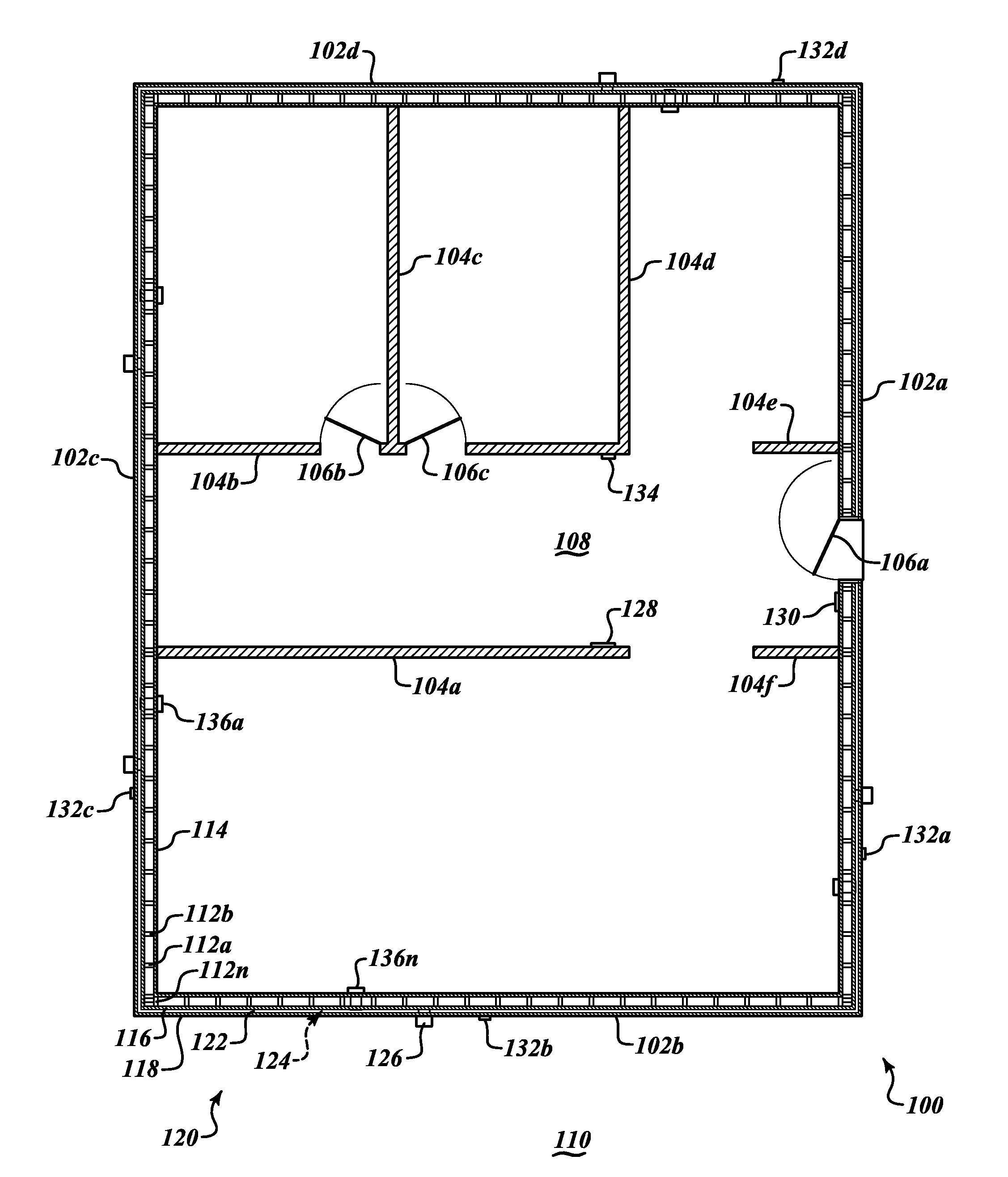
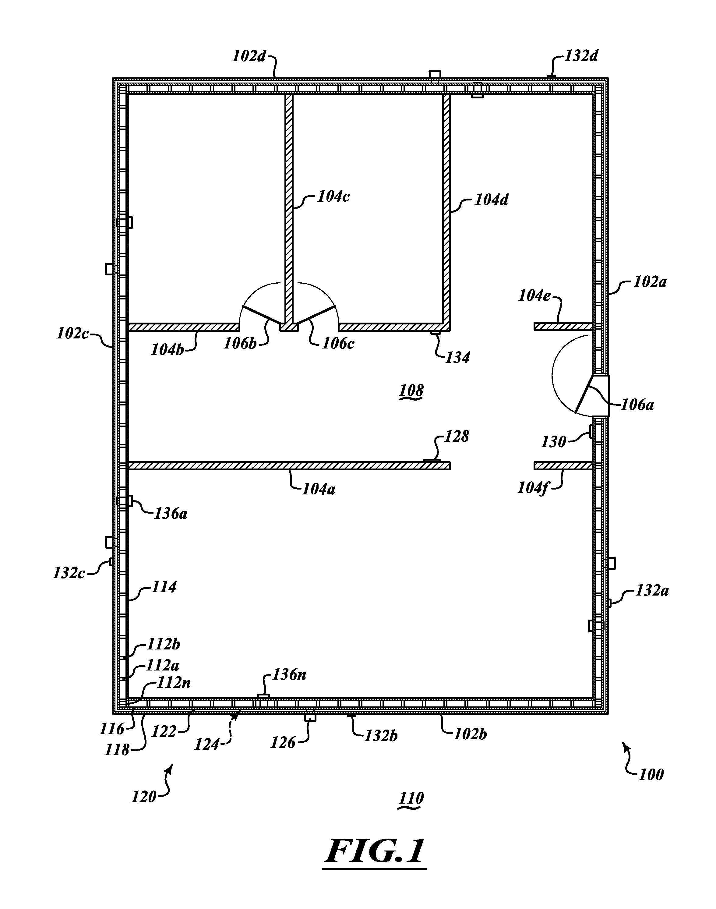
[0070]In a first example, an exterior wall may include steel studs having a depth of 3½ inches, and spaced 16 inches on center. The interior sheathing may be drywall of ½ inch thick with an associated thermal resistance or R value of approximately 0.45. The intermediate sheathing may be DensGlass® sheathing with an R value of approximately 0.56. The exterior wall may include fiberglass batting between the interior sheathing and the intermediate sheathing, having an associated R value of approximately 13. The wall wire lath may provide an air gap of approximately ⅜ inches with an R value of approximately 1.7 for heating and an estimated R value of from approximately 3 to approximately 4 for cooling. The exterior most sheathing may take the form of an approximately 1 inches layer of stucco containing an expanded perlite and having an associated R value of approximately 1. When determining thermal resistance, there is an air film associated with each surface / air interface which air fil...


PUM


Abstract

A building includes exterior walls that form spaces which are selectively vented under control of a control system. Vents are operated to retain trapped air or exhaust trapped air to improve the energy performance of the building. Vents with selectively operable dampers may be located proximate a top of a wall or wall section of wall. Vents may also be located proximate a bottom of a wall or wall section to allow drainage of liquid and circulation of air. Various specific wall constructions provide for an air gap between layers of exterior sheathing of the exterior wall. The air gap may be in addition to a space between interior and exterior sheathing, which space may include a thermal insulation material (e.g., fiberglass batting).

Description

BACKGROUND[0001]1. Technical Field[0002]This disclosure generally relates to the field of building construction and, more particularly, to energy efficient buildings.[0003]2. Description of the Related Art[0004]There is ever increasing concern regarding energy consumption. Reducing energy consumption may provide numerous benefits. For example, such may reduce the costs paid by individual consumers. Such may reduce the infrastructure costs incurred by energy suppliers, for example reducing the number of new generation facilities required. Such may also reduce negative environmental effects, for instance the generation of greenhouse gases or spoilation of the natural environment. In light of such concerns various governmental agencies or departments are promulgating new rules and regulations regarding energy conservation. Various private individuals and business are proposing new approaches and new technologies to address these concerns.[0005]The heating and cooling of buildings is on...

Claims


Application Information

Patent Timeline
Patent Type & Authority Applications(United States)
IPC IPC(8): F24F13/08F24F7/00
CPCF24F5/0075F24F2007/003F24F11/0001F24F2007/0025
Inventor SACKS, ABRAHAM JACOBSPILCHEN, WILLIAMSACKS, JEFFREY LEONARD
Owner SACKS INDAL
Why Eureka
Try Eureka