Clock Distribution in a Distributed System with Multiple Clock Domains Over a Switched Fabric

a distributed system and switched fabric technology, applied in the field of networked devices, can solve the problems of system failure, increased complexity and system cost, and increased system complexity

Active Publication Date: 2012-02-02
NATIONAL INSTRUMENTS
View PDF13 Cites 62 Cited by
  • Summary
  • Abstract
  • Description
  • Claims
  • Application Information

AI Technical Summary

Benefits of technology

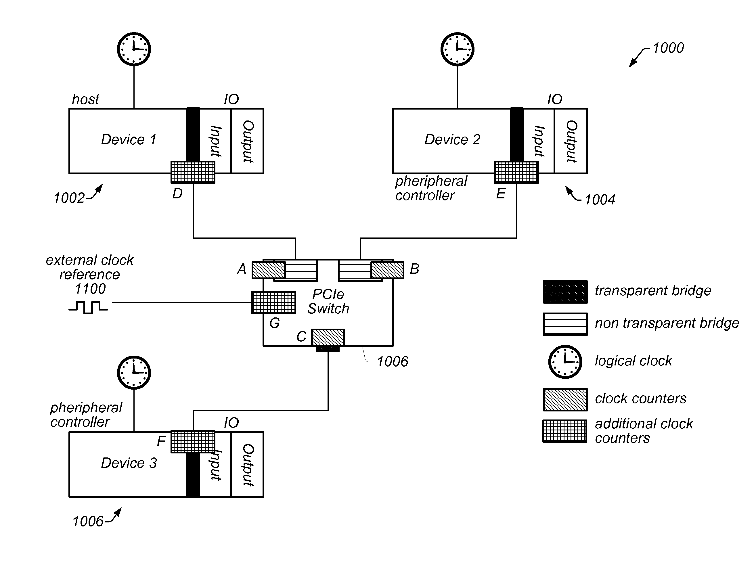
[0012]A time reference for the device relative to the master clock may be determined and stored based on the determined difference. The time reference may then be useable to time stamp events or synchronize future events. In other words, the time reference may be used by the device to operate in synchrony with the master clock, or to time stamp data in accordance with the master clock, or used by some other device, e.g., a master device, to perform some function, e.g., a communication or control function. More generally, the time reference allows the device(s) to operate or to be operated in a manner where timing differences between the device's clock and the master clock are compensated for.
[0013]Thus, embodiments of the present invention may operate to compensate for differences between devices' local clocks and a master clock in a switched fabric-based distributed system.

Problems solved by technology

If a second processor is added, the system operation would fail as both processors attempt to service the system requests.
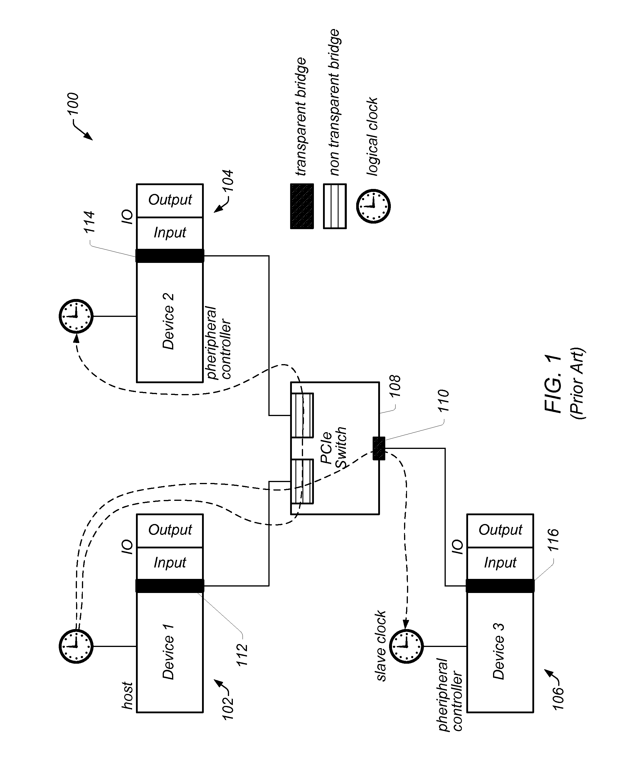
One problem with some switched fabrics, e.g., those utilizing an NTB switch, relates to synchronizing the clocks of devices or processors connected to it.
In prior art approaches to synchronizing 10 connected to each processor or to synchronizing software logic executing on each processor with each other, additional dedicated connections need to be made between the processors and / or IO, which may increase the complexity and expense of the system.

Method used


Image

  • Clock Distribution in a Distributed System with Multiple Clock Domains Over a Switched Fabric
  • Clock Distribution in a Distributed System with Multiple Clock Domains Over a Switched Fabric
  • Clock Distribution in a Distributed System with Multiple Clock Domains Over a Switched Fabric

Examples


Embodiment Construction

Incorporation by Reference

[0028]The following references are hereby incorporated by reference in their entirety as though fully and completely set forth herein:

[0029]U.S. Pat. No. 4,914,568 titled “Graphical System for Modeling a Process and Associated Method,” issued on Apr. 3, 1990.

[0030]U.S. Pat. No. 5,481,741 titled “Method and Apparatus for Providing Attribute Nodes in a Graphical Data Flow Environment”.

[0031]U.S. Pat. No. 6,173,438 titled “Embedded Graphical Programming System” filed Aug. 18, 1997.

[0032]U.S. Pat. No. 6,219,628 titled “System and Method for Configuring an Instrument to Perform Measurement Functions Utilizing Conversion of Graphical Programs into Hardware Implementations,” filed Aug. 18, 1997.

[0033]U.S. Pat. No. 7,210,117 titled “System and Method for Programmatically Generating a Graphical Program in Response to Program Information,” filed Dec. 20, 2000.

TERMS

[0034]The following is a glossary of terms used in the present application:

[0035]Memory Medium—Any of va...


PUM


Abstract

System and method for synchronizing devices. A device reads a first counter coupled to and associated with a master clock and a second counter coupled to and associated with the device, where the device is one of one or more devices coupled to the master clock and each other via a switched fabric, where each device includes a respective clock, and is coupled to and associated with a respective second counter. Each of the first counter and the second counters is accessible by each of the one or more devices. The device determines a difference between the device's associated second counter and the first counter, and determines and stores a time reference for the device relative to the master clock based on the determined difference, where the time reference is useable to timestamp events or synchronize future events.

Description

FIELD OF THE INVENTION[0001]The present invention relates to the field of networked devices, and more particularly to clock distribution in a distributed system with multiple clock domains over a switched fabric.DESCRIPTION OF THE RELATED ART[0002]PCI (Peripheral Component Interconnect) was originally designed as an interconnect for personal computers (PCs). Because of the architecture of PCs, only one processor can control the system. If a second processor is added, the system operation would fail as both processors attempt to service the system requests. PCI-Express (PCIe) was originally conceived as a distributed-clock architecture. A common system clock is distributed to all PCI-Express devices in the system to allow all components in the systems to communicate coherently at gigahertz bit rates while taking advantage of spread-spectrum clocking technology to reduce the peak radiated emissions profile to meet the requirements of various regulatory bodies.[0003]Distributed computi...

Claims


Application Information

Patent Timeline
Patent Type & Authority Applications(United States)
IPC IPC(8): G06F1/14G06F13/42
CPCG06F1/10G06F1/12G06F2213/0038G06F1/14
Inventor CHANDHOKE, SUNDEEPMOHRMANN, LEE E.ULLRICH, ADAM C.GREENSTREET, RODNEY D.
Owner NATIONAL INSTRUMENTS
Why Eureka
Try Eureka