Motor and electric power steering apparatus using motor

Active Publication Date: 2012-02-09
DENSO CORP
View PDF4 Cites 20 Cited by
  • Summary
  • Abstract
  • Description
  • Claims
  • Application Information

AI Technical Summary

Benefits of technology

[0010]Further, a power steering using the motor with the above-described configuration is disclosed. The motor of the present disclosure uses the magnetic sensor that is unaffected by the electric-current-induced magnetic field formed by the conducting wire which connects the winding wire to the control unit. Theref

Problems solved by technology

If the motor has a configuration that arranges the conducting wire closed to the magnetic sensor, the detection result of the magnetic sensor is caused to have an error, thereby deteriorating a detection accuracy.
When the detection accuracy is deteriorated, a torque ripple of the motor may be increased, or loss of output power may

Method used


Image

  • Motor and electric power steering apparatus using motor
  • Motor and electric power steering apparatus using motor
  • Motor and electric power steering apparatus using motor

Examples


first embodiment

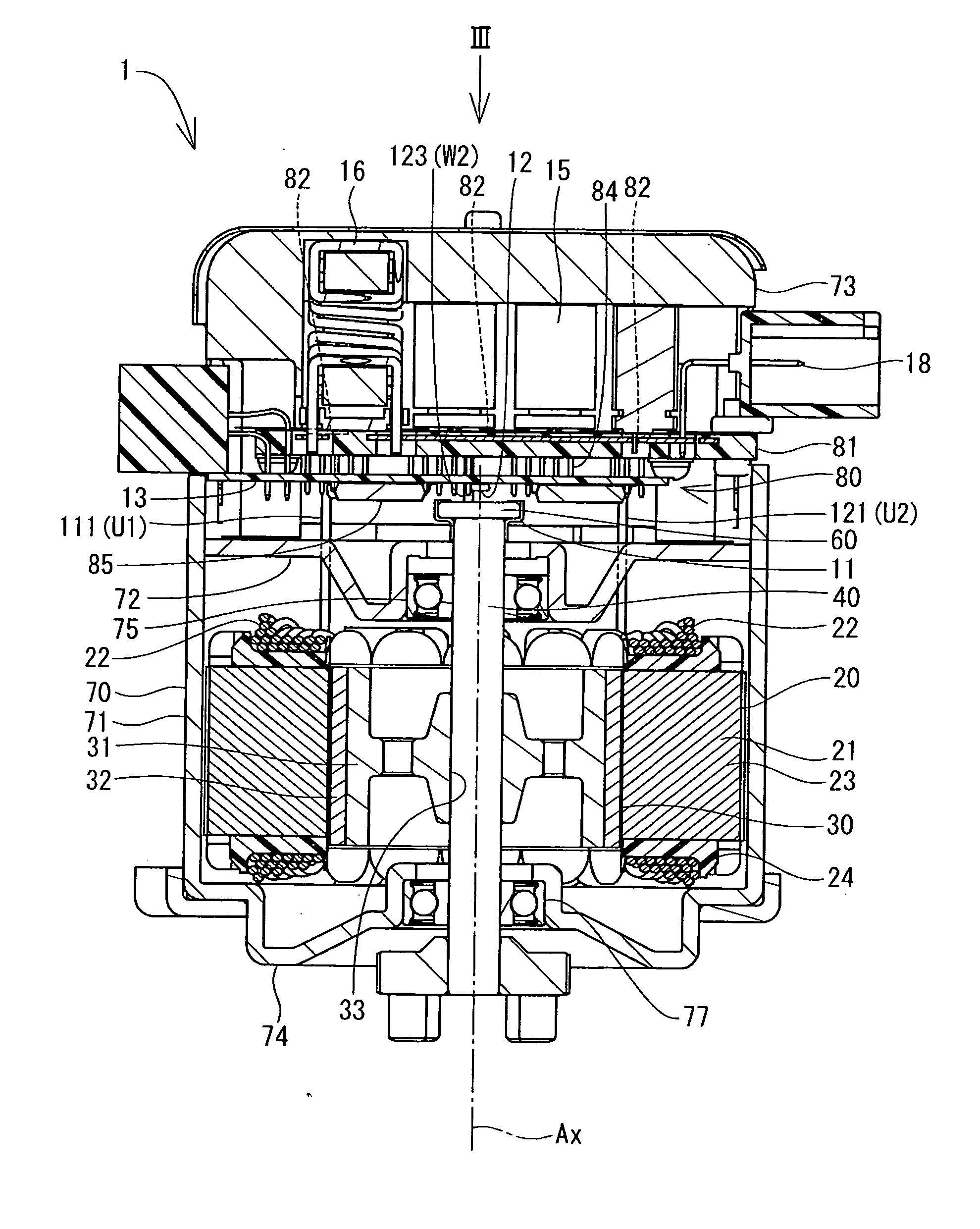
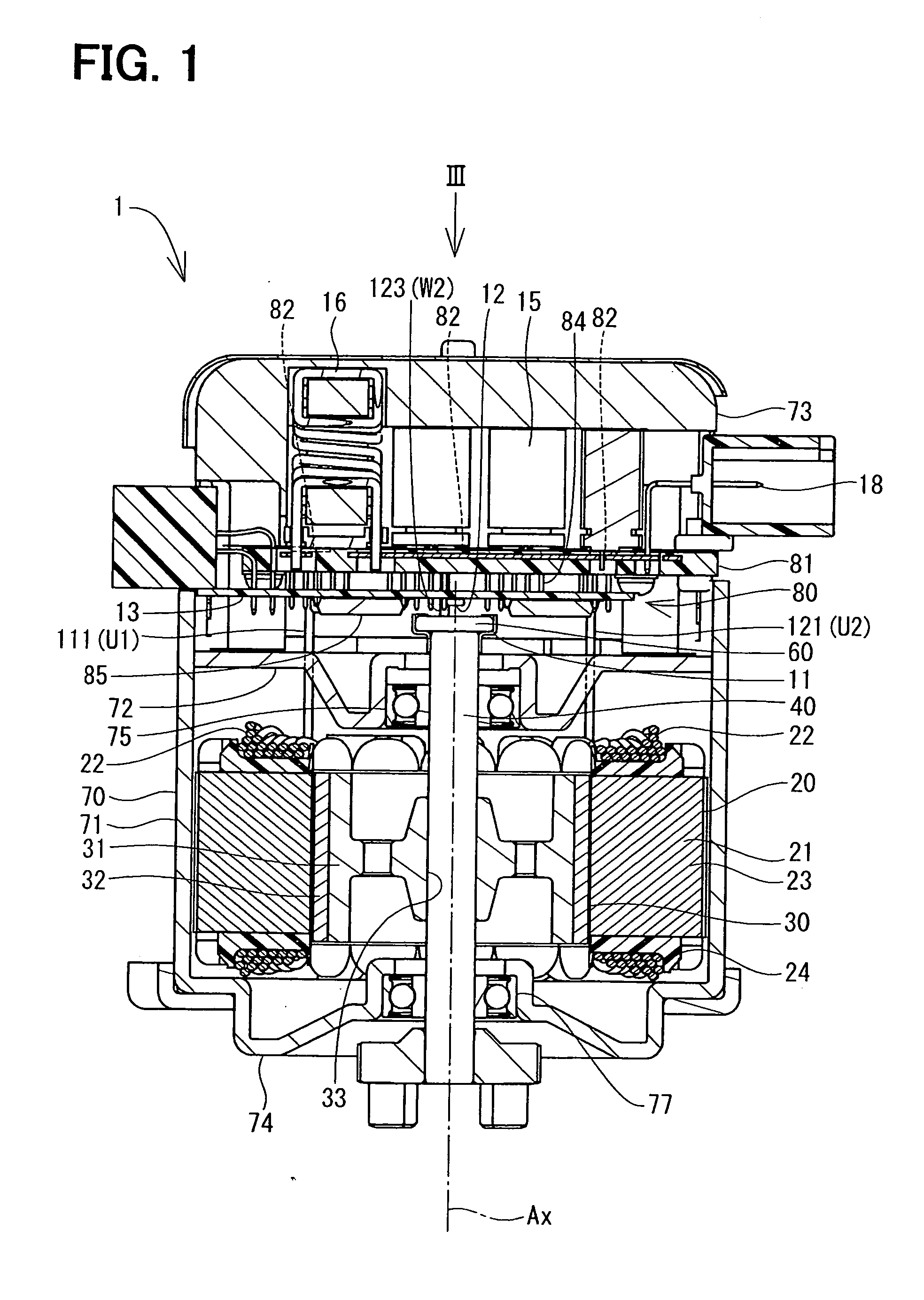
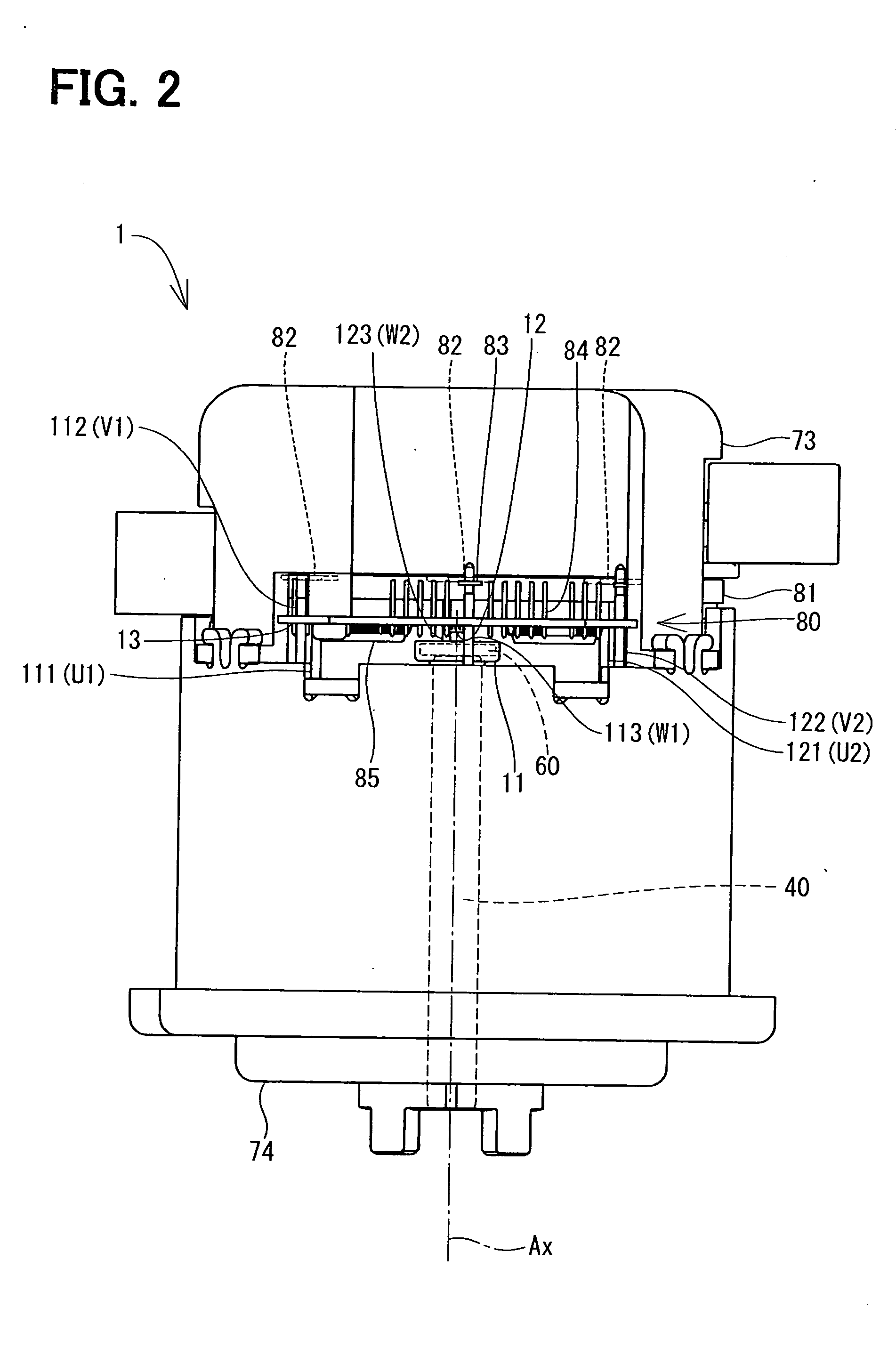
[0018]With reference to FIGS. 1 and 2, a motor 1 is used in an electric power steering apparatus in a vehicle, which is not illustrated, and where the motor 1 provides power assistance steering to a driver of the vehicle.

[0019]The motor 1, with a central axis Ax, includes a stator 20, a rotor 30, a shaft 40, a magnet 60, a magnetic sensor 12, and a control unit 80. The stator 20 includes a plurality of salient poles 21. In the present embodiment, six salient poles 21 are arranged circularly at equal intervals to make the stator 20. The salient pole 21 includes laminated core 23 of layered thin magnetic material and an insulator 24 engaged with the laminated core 23 from a radial direction. Each of the insulators 24 includes a winding wire 22 wound thereon. When the electric power is supplied to the winding wire 22, the salient pole 21 produces magnetic force.

[0020]The rotor 30 is formed with magnetism materials, such as an iron in the shape of a pipe. The rotor 30 includes a rotor c...

second embodiment

[0049]The arrangement of the conducting wires-of the motor in the second embodiment of the present disclosure is illustrated in FIG. 4. Though the schematic configuration of the second embodiment is the same as the first embodiment, difference of the arrangement of the conducting wires connecting the winding wire 22 to the control unit 80 relative to the first embodiment is a focus of the explanation in the following description.

[0050]In the present embodiment, similarly to the first embodiment, each of the U phase conducting wire 111, the V phase conducting wire 112 and the W phase conducting wire 113 in the first system corresponds to “the first conducting wire” in claims. Each of the U phase conducting wire 121, the V phase conducting wire 122 and the W phase conducting wire 123 in the second system corresponds to “the second conducting wire” in claims. Further, each of a pair of the U phase conducting wire 111 and the U phase conducting wire 121, a pair of the V phase conducting...

third embodiment

[0063]The arrangement of the conducting wires of the motor in the third embodiment of the present disclosure is illustrated in FIG. 5. Though the schematic configuration of the third embodiment is the same as the first embodiment, difference of the arrangement of the conducting wires connecting the winding wire 22 to the control unit 80 relative to the first embodiment is a focus of the explanation in the following description.

[0064]In the present embodiment, each of the U phase conducting wire 111 the U phase conducting wire 121 corresponds to “the first conducting wire” in claims, and each of the V phase conducting wire 112 and the V phase conducting wire 122 corresponds to “the second conducting wire” in claims, and each of the W phase conducting wire 113 and the W phase conducting wire 123 corresponds to “the third conducting wire” in claims, which is different from the first embodiment. Further, each of a group of the U phase, conducting wire 111, the V phase conducting wire 11...


PUM


Abstract

A magnetic sensor disposed in an axial direction of a shaft of a motor detects the rotation angle of the rotor by detecting magnetism of the magnet that is disposed on one end of the shaft. A first and second conducting wires extend in parallel with an axis of the shaft, and are equidistantly positioned relative to the axis, on a virtual circle that has a center point on the axis of the shaft. The electric current flowing in the first conducting wire and the electric current flowing in the second conducting wire have the same magnitude and the same flow direction with each other at any time. When the first conducting wire and the second conducting wire are on opposite sides relative to the center point of the virtual circle, the magnetic fields around the conducting wires cancel with each other, thereby enabling accurate detection of the rotation angle.

Description

CROSS REFERENCE TO RELATED APPLICATION[0001]The present application is based on and claims the benefit of priority of Japanese Patent Application No. 2010-177159, filed on Aug. 6, 2010, the disclosure of which is incorporated herein by reference.FIELD OF THE INVENTION[0002]The present disclosure generally relates to a motor having a magnet rotating with a rotor, and an electric power steering that uses the motor.BACKGROUND INFORMATION[0003]Conventionally, a brushless motor or the like that controls electric power supply to a winding wire according to a rotation angle of a rotor has a position sensor for detecting the rotation angle, which is disclosed in WO2008 / 062778 (WO '2778). The position sensor is known to detect a rotation angle in the brushless motor by having a magnet disposed on a rotating part that rotates together with the rotor, and by detecting a magnetic field generated by the magnet with a magnetic sensor such as a Hall element or a magneto-resistive element. In such ...

Claims


Application Information

Patent Timeline
IPC IPC(8): B62D6/00B62D5/04H02K29/08
CPCH02K29/08
Inventor MATSUDA, KUNIHIKO
Owner DENSO CORP
Why Eureka
Try Eureka