Circuit for compensating influence of temperature on a resonator

a technology of resonator circuit and temperature, applied in the direction of piezoelectric/electrostrictive/magnetostrictive devices, piezoelectric/electrostriction/magnetostriction machines, pulse techniques, etc., can solve the problems of mems resonators suffering from one or more of the above drawbacks, heat up the device, etc., and achieve the effect of efficient compensation of the influen

Active Publication Date: 2012-02-09
NXP BV
View PDF2 Cites 14 Cited by
  • Summary
  • Abstract
  • Description
  • Claims
  • Application Information

AI Technical Summary

Benefits of technology

[0009]It is an object of the invention to provide a simple circuit for efficiently compensating the influence of temperature on a resonator circuit, further overcoming one or more of the above drawbacks.
[0018]The advantage as compared to keeping the device bias current low enough to prevent frequency shift by self-heating, may be that in this device, a larger read-out current or voltage signal may be provided. This may give a potential to have less need for feedback amplification, or perhaps even a self-sustaining oscillator without active amplification. Ceramic resonators with a frequency tolerance of more than 3000 ppm over 100K (Kelvin) may be replaced by such a device.
[0026]The supply unit may be coupled to an electric supply voltage internally of the device. This may provide a compact and small device without the need of external supply.
[0029]By having very thin silicon devices, with narrow anchors, it may appear that the heat conductivity is very low. A silicon resonator may only need a limited power dissipation of 10 mW or less in order to be heated by some 100K. The heat conductivity may determine the heat loss and subsequently the heating power to keep the resonance frequency stable. This may be proportional to the thickness of the MEMS anchors. Therefore, the use of thin (1 to 2 um thickness) resonators, like SOI, polysilicon etc, may make it possible to consume around 10 mW of power for stabilizing the resonant frequency over an ambient temperature range of 100K. The thickness may be an advantage as the heat conductivity between heated MEMS device and anchored substrate at ambient temperature may determine the power that is needed to maintain the device at the required resonant frequency.
[0030]The device may be adapted as a monolithically integrated circuit. Thus, the whole circuit plus resonator may be integrated on the same monolithic silicon chip or die. The device may contain an extra external pin for client as a feature to trim the temperature dependent characteristic according to the desires of the client, by adjusting the supply unit, which may be an amplifier, that determines the temperature dependent bias signal or current or bias voltage on the resonator. This may also be combined with another external pin for bias trimming to compensate the process spread.
[0043]Thus, the bias parameter may be trimmed in order to bring the resonant frequency of the device closer to the specified value for a determined reference value of the ambient temperature. An accuracy improvement better than the untrimmed case may bring the absolute resonance frequency closer to the target frequency. Accuracy levels comparable to quartz crystals of 20 ppm or better may be achievable by this method. This trimming at reference temperature may compensate for processing variations of the device resonant frequency, which is a major problem for creating MEMS oscillators on a precise reference frequency. The resulting MEMS resonator may show a reduced frequency spread at reference temperature, for instance 20 ppm plus accuracy of the reference temperature of about 1K, i.e. 30 ppm, on frequency at fixed temperature, but still a temperature drift of 3000 ppm over 100 K.

Problems solved by technology

Due to dissipation, this bias signal will heat up the device.
The prior art MEMS resonators suffer from one or more of the above drawbacks.

Method used


Image

  • Circuit for compensating influence of temperature on a resonator
  • Circuit for compensating influence of temperature on a resonator
  • Circuit for compensating influence of temperature on a resonator

Examples


Embodiment Construction

[0055]The illustration in the drawing is schematically. In different drawings, similar or identical elements are provided with the same reference signs.

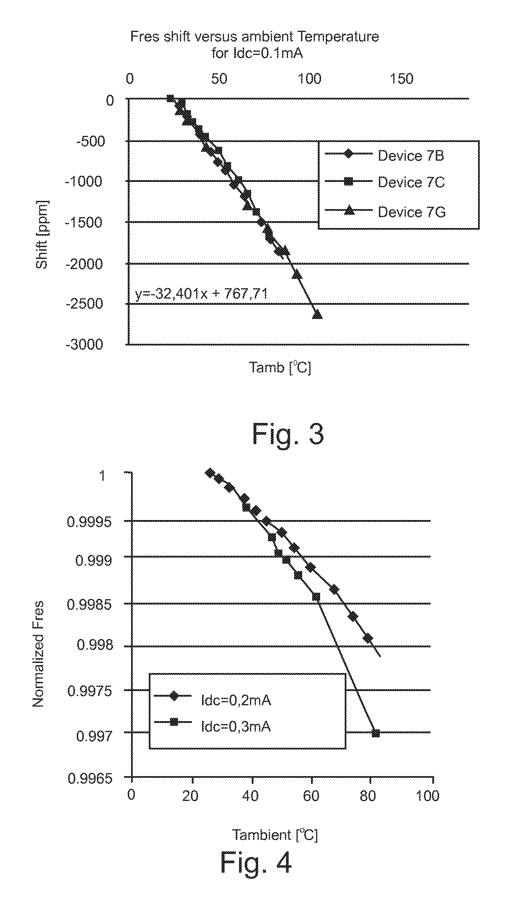
[0056]Referring to FIG. 3, MEMS resonators made of silicon show production spread and a temperature dependent resonant frequency, which is due to the material properties of silicon. MEMS resonant frequency shifts to a lower value if the ambient temperature is increased. The linear behavior is expected from the temperature dependent Young modulus of crystalline silicon. At this current of 0.1 mA, the device does not heat up enough to see a considerable non-linear effect of self heating in the frequency, ie it is mainly linear.

[0057]In the concept of the piezo-resistive MEMS resonator the oscillation results in an oscillating value for the resistance δR / R (which has to be read as delta R / R) due to the piezo-resistive effect. This effect describes the dependency of the electrical conductivity in the MEMS resonator on the strain in the r...


PUM


Abstract

The invention relates to a device for compensating influence of temperature on a resonator circuit. The device comprises a resonator circuit and a supply unit for supplying an electric bias signal to the resonator circuit, wherein the supply unit is adapted for adjusting the electric bias signal for compensating influence of temperature on the resonator circuit.

Description

FIELD OF THE INVENTION[0001]The invention relates to a circuit for compensating influence of temperature on a resonator circuit.[0002]Beyond this, the invention relates to a method of compensating influence of a temperature on a resonator circuit.[0003]Moreover, the invention relates to a program element.[0004]Furthermore, the invention relates to a computer-readable medium.BACKGROUND OF THE INVENTION[0005]In the field of radios, telecommunications, computers and other electronic applications, devices may comprise resonators for providing a resonator frequency. Such resonators may be used in Micro-Mechanical-Systems. Micro-Electro-Mechanical Systems may be denoted as the technology of the very small members, and merges at the nano-scale into nano-electromechanical systems (NEMS) and nanotechnology. MEMS may be made up of components between 1 μm to 100 μm in size and MEMS devices may generally range in size from 20 μm to 1 mm.[0006]Resonators, in particular MEMS resonators are typica...

Claims


Application Information

Patent Timeline
Patent Type & Authority Applications(United States)
IPC IPC(8): H01L41/107
CPCH03H9/02448H03K3/3545H03K3/011
Inventor KONING, JAN JACOBWU, DIBONTEMPS, JOEP
Owner NXP BV
Why Eureka
Try Eureka