Battery charging control device and battery charging control method for electric vehicle

a charging control and electric vehicle technology, applied in the direction of battery/fuel cell control arrangement, hybrid vehicles, battery/cell propulsion, etc., can solve the problem that the battery charging control cannot be executed

Active Publication Date: 2012-02-09
NISSAN MOTOR CO LTD
View PDF8 Cites 71 Cited by
  • Summary
  • Abstract
  • Description
  • Claims
  • Application Information

AI Technical Summary

Problems solved by technology

In this case, battery charging control cannot be executed.

Method used


Image

  • Battery charging control device and battery charging control method for electric vehicle
  • Battery charging control device and battery charging control method for electric vehicle
  • Battery charging control device and battery charging control method for electric vehicle

Examples


Embodiment Construction

[0032]An embodiment of this invention will be described below with reference to the drawings.

[0033][Power Train]

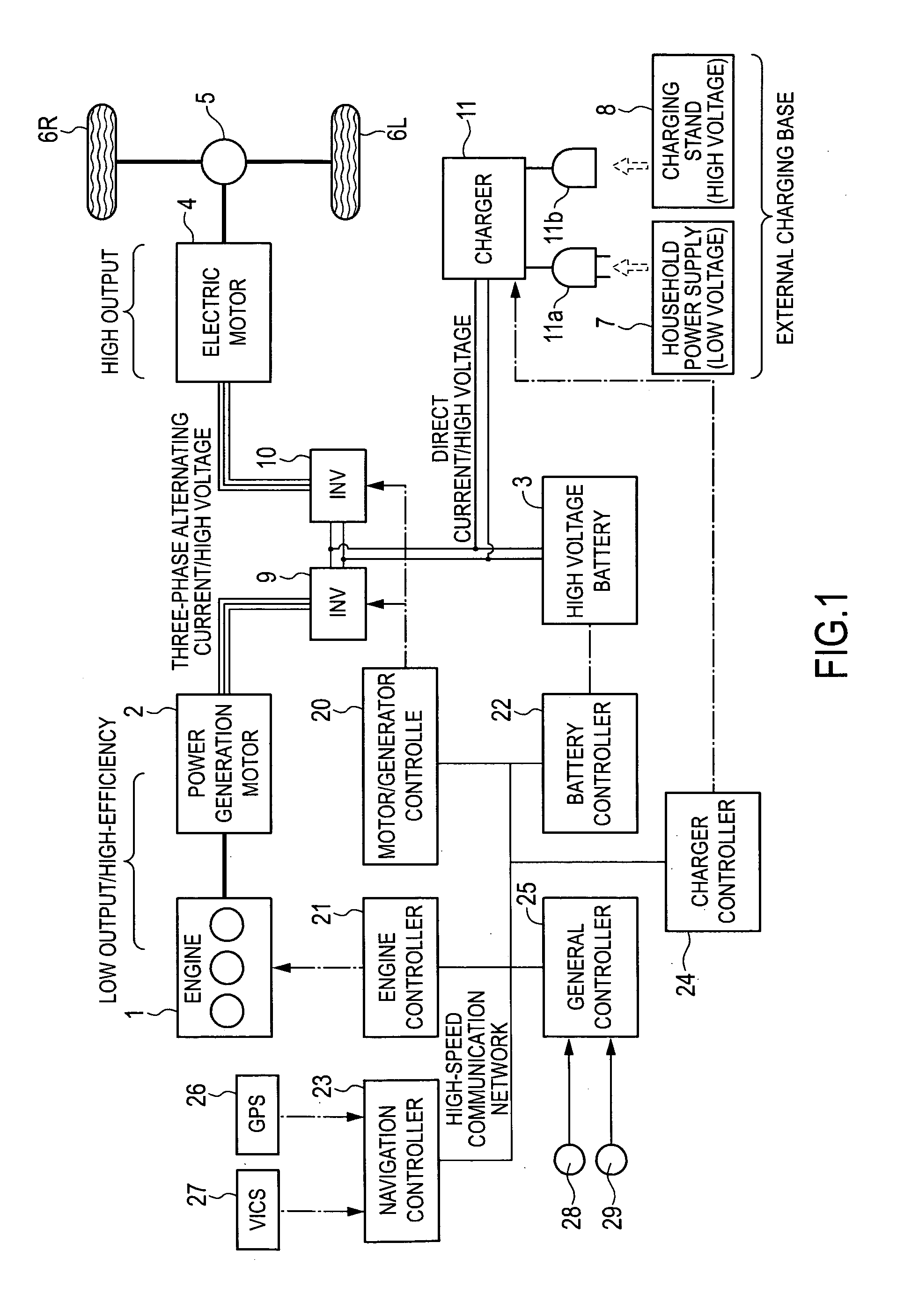
[0034]FIG. 1 is a schematic system diagram showing a power train and a control system of a hybrid electric vehicle to which this invention is applied.

[0035]A hybrid electric vehicle (“HEV” hereafter) shown in FIG. 1 is a series type HEV in which a battery can be charged by an external power supply. It should be noted that this invention may also be applied to a parallel type HEV or a compound type HEV. This invention may also be applied to an HEV that is not charged by an external power supply.

[0036]The HEV shown in FIG. 1 includes an engine 1, a power generation motor 2, an inverter 9, a battery 3, an inverter 10, an electric motor 4, a final reduction gear 5, a left drive wheel 6L, a right drive wheel 6R, and a charger 11.

[0037]The engine 1 drives the power generation motor 2. The power generation motor 2 generates power when driven by the engine 1. The power generation ...


PUM


Abstract

A battery charging control device for controlling a power generation device installed in an electric vehicle sets a battery energy management area using a current position of a host vehicle as a reference, detects at least one travelable route within the battery energy management area, calculates a battery energy management upper limit value and a battery energy management lower limit value on the basis of a maximum value and a minimum value of energy values required to travel to respective points on the travelable route from the current position, and calculates a battery energy management width by subtracting the management lower limit value from the management upper limit value. When the battery energy management width is not within a predetermined range, the battery energy management area is modified so as to enter the predetermined range. As a result, battery charging is controlled such that a magnitude relationship between the battery energy management upper limit value and the battery energy management lower limit value does not reverse.

Description

TECHNICAL FIELD[0001]This invention relates to a device and a method for controlling charging of a battery installed in an electric vehicle.BACKGROUND ART[0002]JP3417389B, published by the Japan Patent Office in 2003, discloses a device for controlling a power generation device installed in a hybrid electric vehicle in order to control charging of a battery.[0003]This battery charging control technique uses road information such as a travel route, a travel distance and an altitude obtained from a car navigation system. A battery energy management upper limit value and a battery energy management lower limit value are set such that before a downhill slope, a remaining battery energy is as low as possible and before an uphill slope, the remaining battery energy is as high as possible.SUMMARY OF THE INVENTION[0004]However, depending on operating conditions of the vehicle, the battery energy management lower limit value may be larger than the upper limit value. In this case, battery cha...

Claims


Application Information

Patent Timeline
Patent Type & Authority Applications(United States)
IPC IPC(8): H02J7/00B60L50/15B60L50/16
CPCB60K6/46Y02T90/121B60L11/185B60L11/1861B60L2240/423B60L2240/62B60L2240/64B60W10/06B60W10/08B60W10/26B60W20/00B60W2510/244B60W2520/10B60W2540/10B60W2550/143B60W2550/402B60W2710/0666B60W2710/083B60W2710/086Y02T10/6217Y02T10/6269Y02T10/6286Y02T10/642Y02T10/7005Y02T10/7044Y02T10/705Y02T10/7077Y02T10/7088Y02T10/7291Y02T90/128Y02T90/14Y02T90/16Y02T90/162Y02T10/90B60L11/123Y02T10/7072B60L50/61B60L53/11B60L58/12B60W2552/20B60W2556/50Y02T10/62Y02T10/64Y02T10/70Y02T10/72B60K2006/268B60W2555/40B60W2552/25Y02T90/12B60W2050/0075
Inventor KOTOOKA, SEIJIRONAKAMURA, HIDEOSEGAWA, SATOSHI
Owner NISSAN MOTOR CO LTD
Why Eureka
Try Eureka