Method for detecting loss of sensitivity of an fmcw radar locating device by diffuse sources of loss

a technology of fmcw radar and loss detection, which is applied in the direction of measuring devices, using reradiation, instruments, etc., can solve the problems of reducing the transmit and receive power of radar sensors, reducing detection depth and reliability, and easily forming losses on the surface of radomes

Active Publication Date: 2012-02-09
ROBERT BOSCH GMBH
View PDF11 Cites 17 Cited by
  • Summary
  • Abstract
  • Description
  • Claims
  • Application Information

AI Technical Summary

Benefits of technology

[0014]An object of the present invention is to provide a method for detecting diffuse sources of loss that is more robust against such disturbing influences.

Problems solved by technology

A radome that covers the antenna and is mostly formed by a radar lens is exposed to a particularly high degree to weather influences and street dirt, so that a reflective dielectric coating (a film of dirt or water) that causes losses can easily form on the surface of the radome.
This significantly reduces the transmit and receive power of the radar sensor, so that detection depth and reliability are significantly limited, up to the complete blinding of the radar sensor.
A coating on the radome is therefore an example of a “diffuse source of loss” that can significantly impair the sensitivity of the radar locating system.
However, a disadvantage of this method is that the average power is a function not only of the presence of diffuse sources of loss, but also of a large number of other factors, including, among others, specific properties of the respective radar sensor, assembly and installation tolerances of the radar sensor when installed in the motor vehicle, and in particular influences of temperature and aging.
If, however, a large number of real objects are located at different distances, as can happen for example when traveling in alleys or tunnels, or when traveling directly alongside a truck, the corresponding object peaks are distributed so tightly in the spectrum that the detection threshold is raised, with the consequence that it is no longer possible to reliably distinguish between the objects and the rain clutter.
In addition, the effectiveness of this method is limited by disturbing factors such as installation tolerances, temperature, and aging.
However, it turns out that the diffuse sources of loss not only influence the absolute power of the received signal, but also affect the manner in which the power of the received signal reacts to changes in the transmit power.

Method used


Image

  • Method for detecting loss of sensitivity of an fmcw radar locating device by diffuse sources of loss
  • Method for detecting loss of sensitivity of an fmcw radar locating device by diffuse sources of loss
  • Method for detecting loss of sensitivity of an fmcw radar locating device by diffuse sources of loss

Examples


Embodiment Construction

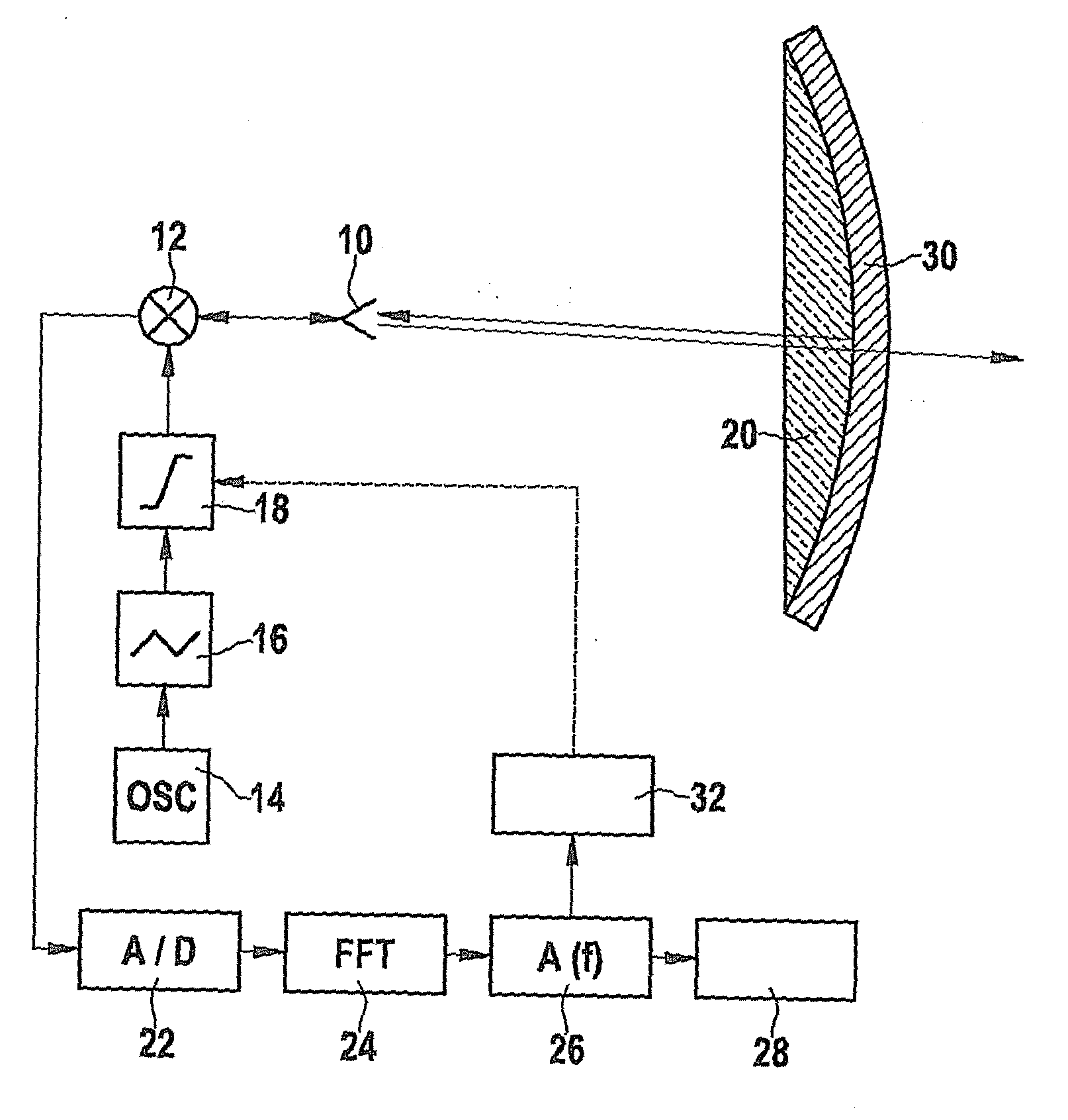
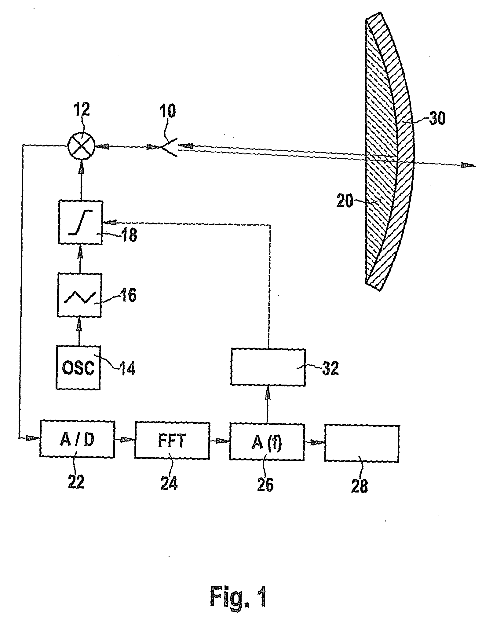
[0031]The radar locating device shown in FIG. 1 has an antenna 10 to which, via a mixer 12, a transmit signal is supplied that is produced by an oscillator 14 and is frequency-modulated by a modulator 16. Moreover, FIG. 1 symbolically shows an amplifier 18 with which the power of the transmit signal can be varied. In practice, however, this power variation can also take place in the oscillator or in the modulator. The signal emitted by antenna 10 is focused by a radar lens that here forms at the same time a radome 20 that covers the antenna and thus protects the antenna against weather influences.

[0032]If an object (not shown) is located by the radar locating device, the signal reflected by the object is focused by the lens onto the same antenna 10 that emitted the transmit signal (monostatic antenna design). In mixer 12, the received signal is mixed with a portion of the transmit signal, and as a mixed product a time-dependent signal (intermediate frequency signal) is obtained that...


PUM


Abstract

A method for the detection of sensitivity losses of an FMCW radar locating device due to diffuse sources of loss, in which the radar locating device emits a transmit signal whose frequency is periodically modulated in successive modulation ramps, and at least one power characteristic of at least one frequency portion of a signal received by the radar locating device is evaluated, wherein the power of the transmit signal is varied cyclically, in each case after the completion of a modulation ramp, and the sensitivity losses are determined on the basis of differences in the power characteristics of signals received during successive modulation ramps having identical modulation.

Description

FIELD OF THE INVENTION[0001]The present invention relates to a method for detecting losses of sensitivity of an FMCW radar locating device by diffuse sources of loss, in which the radar locating device emits a transmit signal whose frequency is periodically modulated in successive modulation ramps, and at least one power characteristic of at least one frequency portion of a signal received by the radar locating device is evaluated.BACKGROUND INFORMATION[0002]FMCW radar locating devices are frequently used in driver assistance systems for motor vehicles, for example for automatic distance control or for early recognition of the risk of a collision. A radome that covers the antenna and is mostly formed by a radar lens is exposed to a particularly high degree to weather influences and street dirt, so that a reflective dielectric coating (a film of dirt or water) that causes losses can easily form on the surface of the radome.[0003]This significantly reduces the transmit and receive pow...

Claims


Application Information

Patent Timeline
Patent Type & Authority Applications(United States)
IPC IPC(8): G01S13/00G01S13/931
CPCG01S7/4004G01S13/345G01S2007/4039G01S13/95G01S13/931G01S7/4039
Inventor HEILMANN, STEFANKUEHNLE, GOETZBECHLER, DIRK
Owner ROBERT BOSCH GMBH
Why Eureka
Try Eureka