Engine and pod assembly for an aircraft, equipped with an Anti-icing device

a technology of pods and pods, which is applied in the direction of machines/engines, transportation and packaging, combustion air/fuel air treatment, etc., can solve the problems of asymmetry of rotation of ice layers and rough off-balance, and achieve the effect of improving the efficiency of anti-icing devices, reducing consumption, and easy integration

Active Publication Date: 2012-02-16
SN DETUDE & DE CONSTR DE MOTEURS DAVIATION S N E C M A +1
View PDF9 Cites 3 Cited by
  • Summary
  • Abstract
  • Description
  • Claims
  • Application Information

AI Technical Summary

Benefits of technology

[0012]One object of the invention is to provide means for improving the efficiency of...

Problems solved by technology

The result is an asymmetry of rotation of the ice layer.
This causes a rough off...

Method used


Image

  • Engine and pod assembly for an aircraft, equipped with an Anti-icing device
  • Engine and pod assembly for an aircraft, equipped with an Anti-icing device

Examples


Embodiment Construction

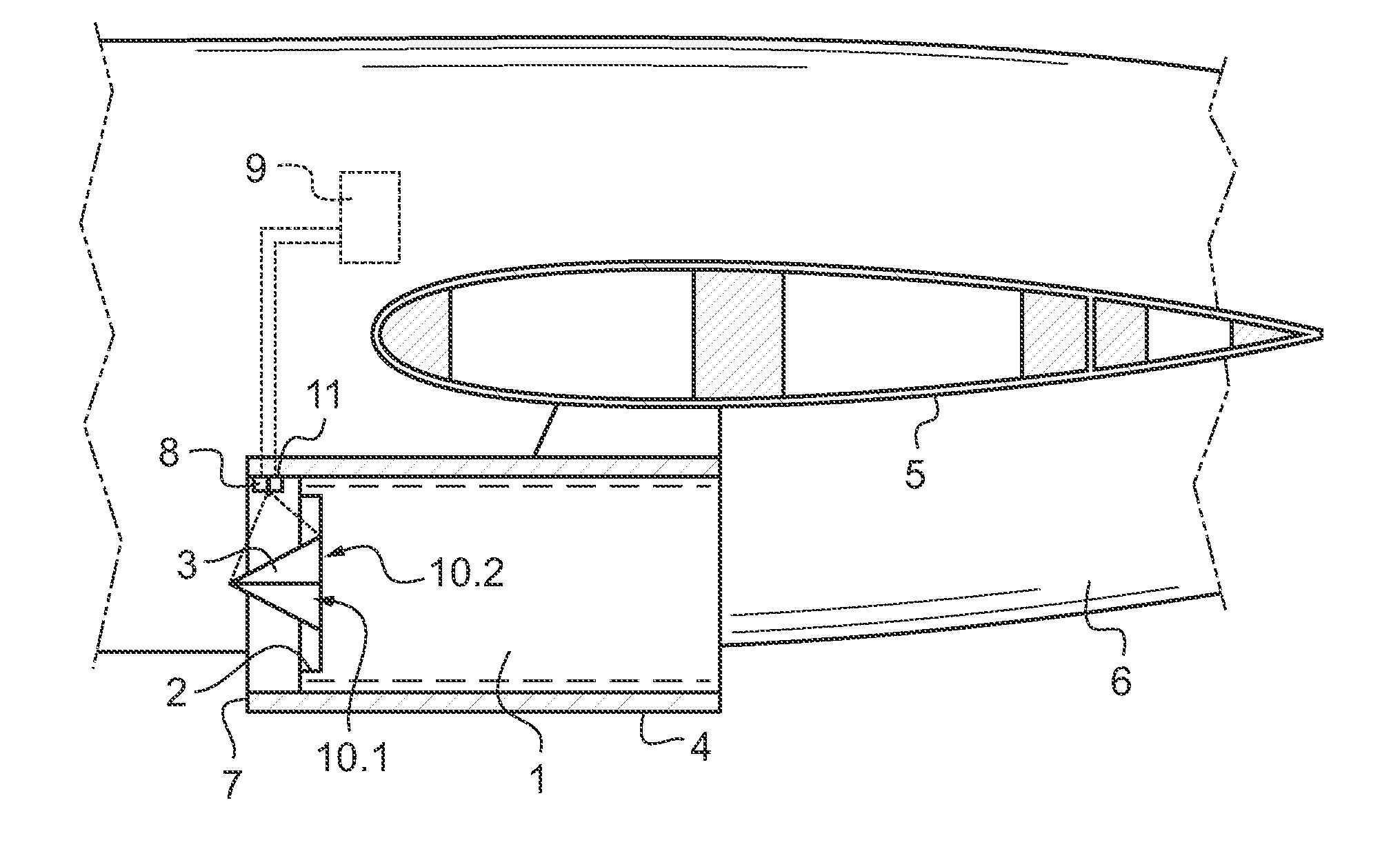
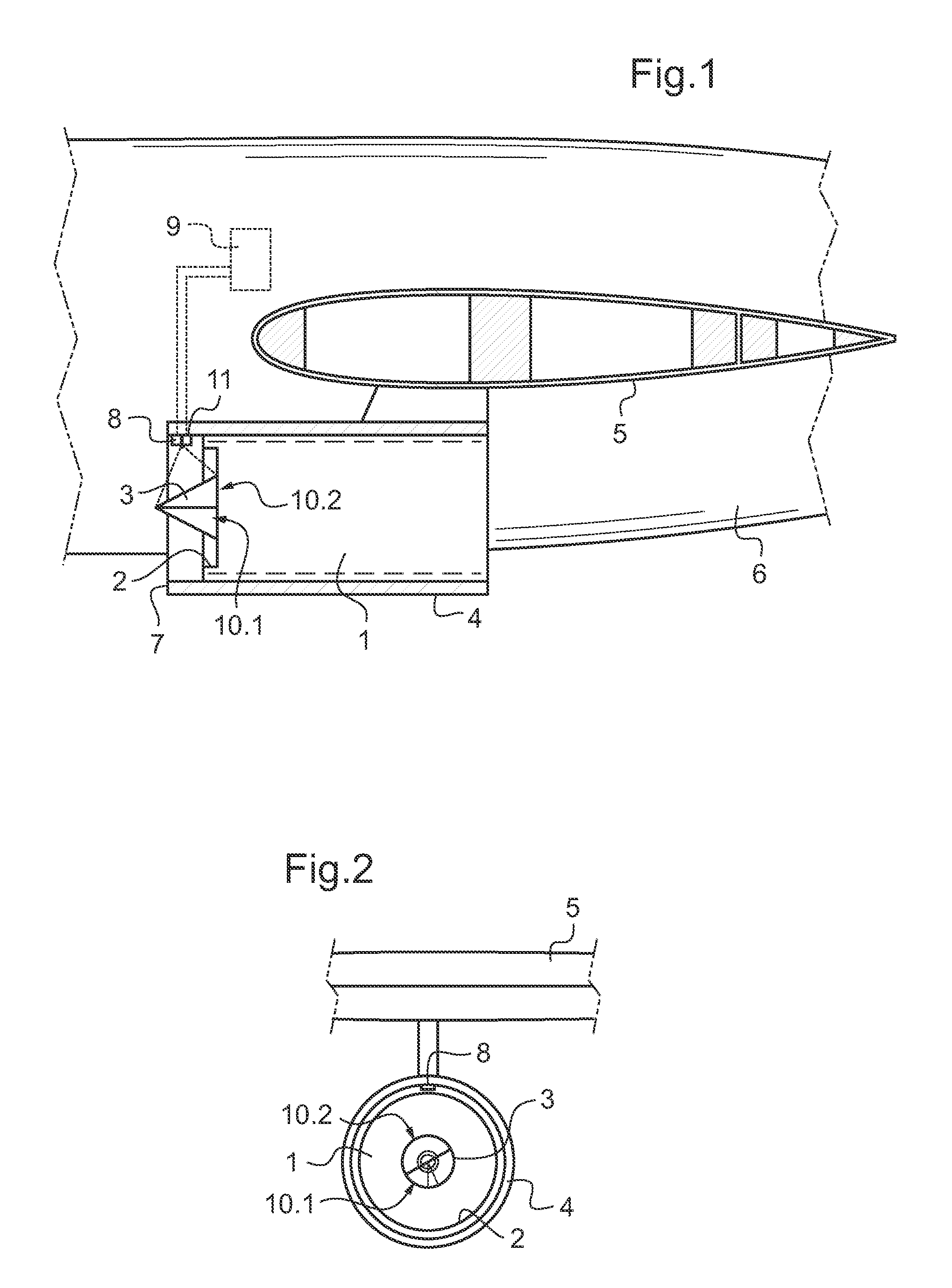
[0030]While referring to the figures, an assembly according to the invention includes an engine of the turbojet type indicated by 1. The engine 1 successively and axially includes an inlet 2, a compressor, a combustion chamber, a turbine and an exhaust nozzle. In the inlet 2 is mounted a nose cone 3 fixed to a shaft driven into rotation by the turbine of the engine 1. The engine 1 is roughly symbolised by a rectangle and will not be described here since the structure thereof is known per se and is not the subject of the present invention.

[0031]The assembly includes a pod 4 receiving the engine 1. The pod 4 is fixed to a wing 5 of said aircraft 6 and includes a leading edge 7 surrounding the inlet opening 2 of the engine 1.

[0032]Finally, the assembly includes a device for limiting the formation of ice on the nose cone 3.

[0033]Here this device includes means associated with the nose cone 3 and means associated in the vicinity of the leading edge 7 of the pod 4.

[0034]In the vicinity of...


PUM


Abstract

An engine and pod assembly for an aircraft includes a pod receiving an engine having an air intake. A rotating nose cone extends on the nose cone, as well as a device for limiting the formation of ice. The device includes means for creating a circumferential heterogeneity of ice on the nose cone.

Description

BACKGROUND OF THE INVENTIONFIELD OF THE INVENTION[0001]The present invention relates to an engine and pod assembly for an aircraft. The invention is more particularly adapted to jet engines and other turbojet engines.[0002]An engine for an aircraft of the straight flow turbojet or double fan types includes an air intake, a compressor with several stages, a combustion chamber, a compressor-driving turbine and a jet pipe propelling nozzle. In the air intake, an inlet nose cone extends which is mounted on a shaft driven into rotation by the turbine. The engine is received in a pod fixed to the aircraft.[0003]It is known that the formation of ice, more particularly on the nose cone of the motor, is a risk for the motor when pieces of ice of a relatively significant size detach from the nose cone of the engine and go into the compressor where they may deteriorate the blades. Ice may form when the aircraft flies through freezing fog or a particularly cold cloud or during flying very low i...

Claims


Application Information

Patent Timeline
IPC IPC(8): F02C7/04
CPCB64D15/00B64D29/00F02C7/047
Inventor DUFRESNE DE VIREL, FRANCOISPEALAT, MICHELJOYEZ, PATRICKPONTOIZEAU, BRUCELACUISSE, JEAN-FRANCOISWINTENBERGER, SYLVIE
Owner SN DETUDE & DE CONSTR DE MOTEURS DAVIATION S N E C M A
Why Eureka
Try Eureka