
Opposed-piston engine having a single crankshaft coupled to the opposed pistons by linkages with pivoted rocker arms

a technology of opposed pistons and crankshafts, which is applied in the direction of connecting rod bearings, machines/engines, and connecting rod bearings. it can solve the problems of limiting the durability affecting the operation efficiency of piston-to-crankshaft connecting links, and uninterrupted application of compressive loads on bearings. it reduces the lubricant-blocking effect of non-reversing loads and improves the durability of bearings

Active Publication Date: 2012-02-16
ACHATES POWERS INC
View PDF11 Cites 12 Cited by
  • Summary
  • Abstract
  • Description
  • Claims
  • Application Information

AI Technical Summary

Benefits of technology

[0009]An object is to a provide rocker arm bearing construction that alleviates the lubricant-blocking effects of non-reversing loads and increases the durability of the bearings. Preferably, a full contact rocker arm bearing distributes compressive loads generated by combustion across the entire face of a pivot pin.
[0010]Another object is to provide a VCR system for a single-crankshaft opposed piston engine with a rocker-type linkage that utilizes a rotatable pivot bearing with an eccentric aspect in a simple and compact VCR system construction in which the pivot shaft is stationary. Preferably, the VCR system is actuated by a computer-controlled mechanism so as to respond automatically to changing engine conditions.

Problems solved by technology

In some aspects of two-stroke, opposed-piston construction, the nature of the operating cycle results in the uninterrupted application of compressive loads on bearings in the piston-to-crankshaft connecting linkages.
These non-reversing loads prevent the separation of bearing surfaces, which blocks the flow of lubricant therebetween and limits the durability of such bearings.
A high compression ratio generally improves engine operating efficiency but is limited by the high structural loads that result at high power conditions.
However, the VCR mechanism described in this patent utilizes a complex, manually-actuated construction that does not respond automatically to changing engine conditions.

Method used


Image

  • Opposed-piston engine having a single crankshaft coupled to the opposed pistons by linkages with pivoted rocker arms
  • Opposed-piston engine having a single crankshaft coupled to the opposed pistons by linkages with pivoted rocker arms
  • Opposed-piston engine having a single crankshaft coupled to the opposed pistons by linkages with pivoted rocker arms

Examples


Embodiment Construction

[0025]The invention described in this specification is presented in an explanatory context that includes a ported, uniflow scavenging engine having at least one cylinder in which a pair of pistons is disposed with their end surfaces in opposition. This explanatory context is intended to provide a basis for understanding various embodiments of the invention by way of illustrative examples that are not meant to prevent application of the invention to other internal combustion constructions.

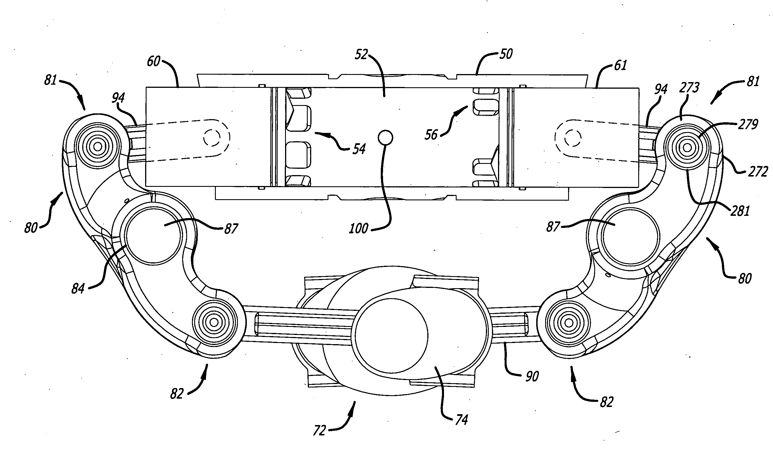
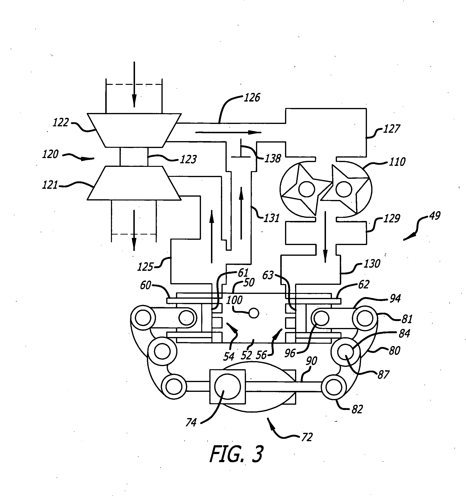
[0026]In FIG. 3, an internal combustion engine 49 is embodied by an opposed-piston engine having at least one cylinder 50. For example, the engine may have two cylinders, three cylinders, or four or more cylinders. Each cylinder 50 has a bore 52 and exhaust and intake ports 54 and 56 formed or machined in respective ends thereof. The exhaust and intake ports 54 and 56 each include a circumferential ring of openings in which adjacent openings are separated by a solid bridge. (In some descriptions, ea...


PUM


Abstract

An opposed-piston engine with a single crankshaft has a rocker-type linkage coupling the crankshaft to the pistons that utilizes a rotatable pivot rocker arm with full-contact plain bearings. A rocker-type linkage utilizes a rotatable pivot bearing with an eccentric aspect to vary translation of piston linkage along the axial direction of a cylinder, which shifts the top dead center (TDC) and bottom dead center (BDC) locations of a piston so as to change the volume of charge air compressed during the power stroke.

Description

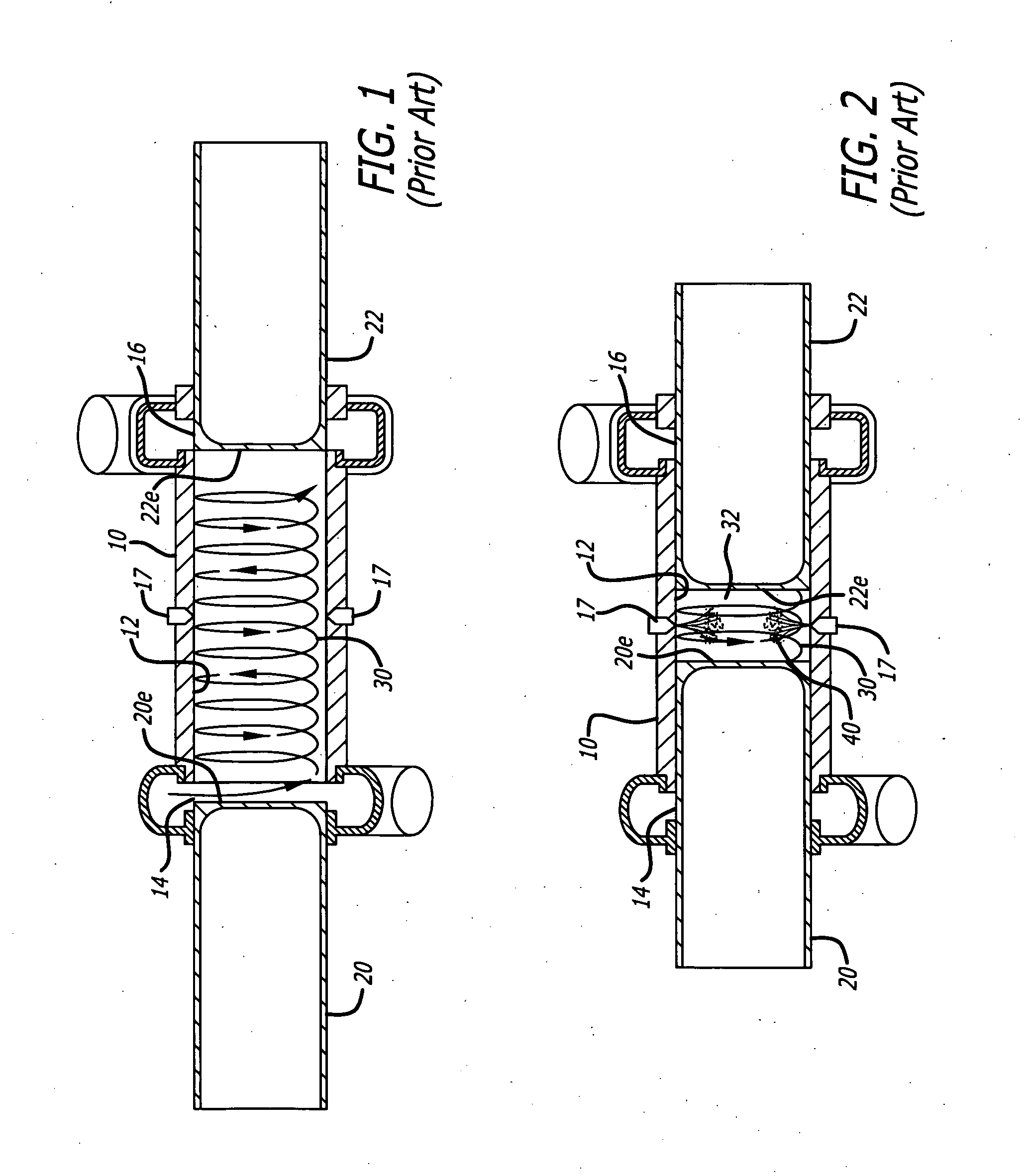
RELATED APPLICATIONS AND PRIORITY[0001]This application claims priority to U.S. provisional application Ser. No. 61 / 401,598, filed Aug. 16, 2010.BACKGROUND[0002]The field is internal combustion engines. Particularly, the field relates to two-stroke engines with ported cylinders; in more particular applications, the field relates to a ported, opposed-piston engine with a single crankshaft that is coupled to the opposed pistons by linkages with pivoted rocker arms.[0003]Per FIG. 1, an opposed-piston engine includes at least one cylinder 10 with a bore 12 and longitudinally-displaced intake and exhaust ports 14 and 16 machined or formed therein. One or more fuel injectors 17 are secured in injector ports (ports where injectors are positioned) that open through the side surface of the cylinder. Two pistons 20, 22 according to the prior art are disposed in the bore 12 with their end surfaces 20e, 22e in opposition to each other. For convenience, the piston 20 is denominated as the “intak...

Claims


Application Information

Patent Timeline
IPC IPC(8): F02B75/28F16H21/32
CPCY10T74/182Y02T10/144F01B7/08F01B7/12F02B23/0621F02B23/0624F02B23/0663F02B23/0675F02B25/08F02B29/0406F02B33/38F02B37/04F02B75/04F02B75/282F02B75/32F16C9/04F16C33/08F02M26/08F02B75/28F16H21/32Y02T10/146Y02T10/125F16H21/34Y02T10/12
Inventor FUQUA, KEVIN B.
Owner ACHATES POWERS INC
Learn More