
Solar cell module, solar cell attachment stand, photovoltaic power generating system

a solar cell and solar panel technology, applied in the direction of machine supports, heat collector mounting/supports, light and heating apparatus, etc., can solve the problem of brittleness of the solar panel itself, and achieve the effect of reducing the number of pieces, simple structure, and facilitating the attemp

Inactive Publication Date: 2012-02-16
SHARP KK
View PDF1 Cites 33 Cited by
  • Summary
  • Abstract
  • Description
  • Claims
  • Application Information

AI Technical Summary

Benefits of technology

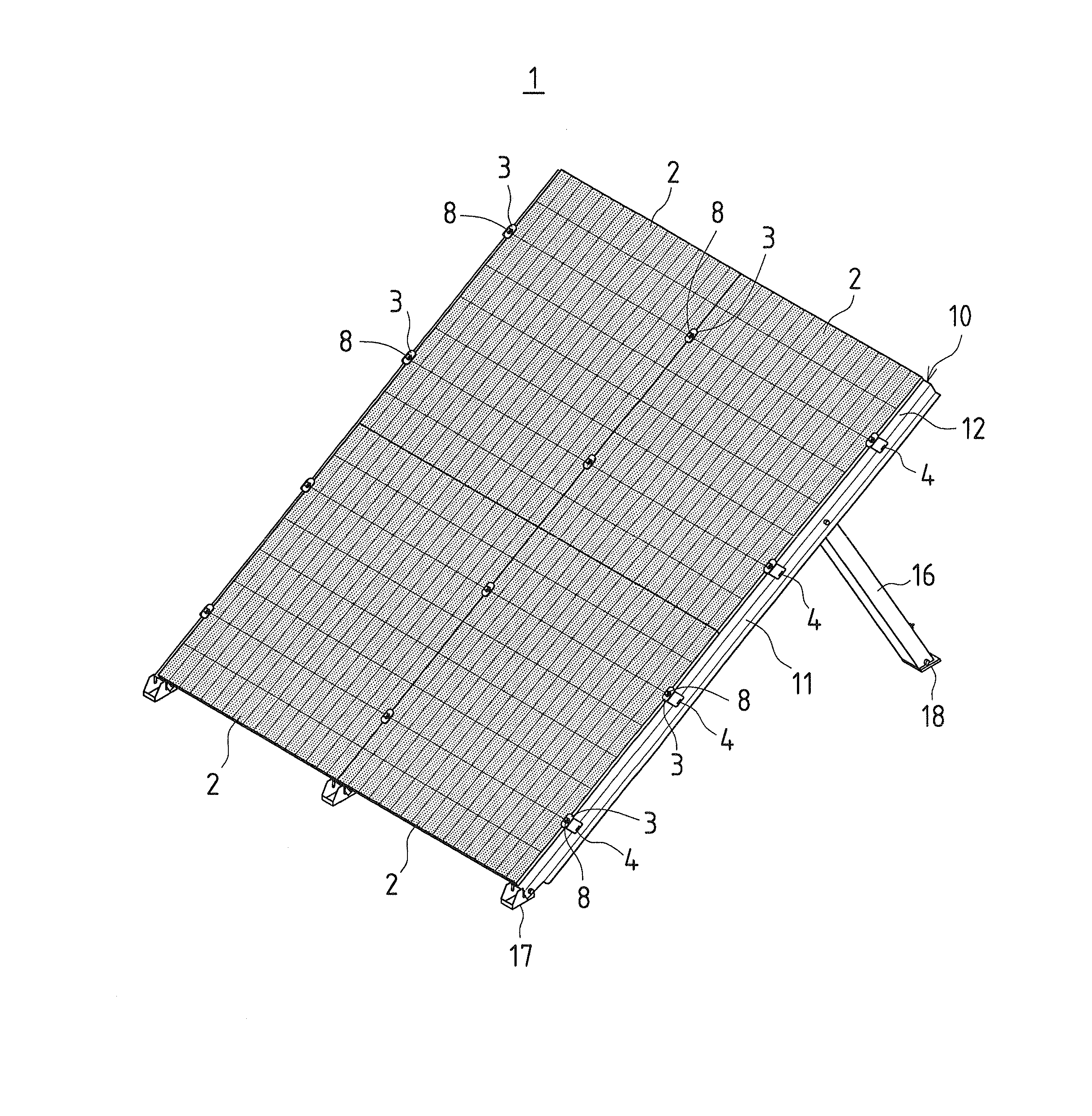
The present invention provides a solar cell module, a solar cell attachment stand, and a photovoltaic power generating system that protect a solar cell panel and facilitate the attachment of the solar cell panel on a roof and the like, even without use of a frame member to hold the solar cell panel. The solar cell panel is reinforced with a reinforcing member that is adhered to the rear surface of the solar cell panel and secured across opposing two sides of the solar cell panel. The reinforcing member includes an engagement portion protruding from the rear surface of the solar cell panel. The solar cell module has a simple structure with a reduced piece-part count and facilitates the attempt to reduce weight and cost of the solar cell module. The reinforcing member may also include hooking portions bent at both ends of the reinforcing member to prevent damage to the sides of the solar cell panel when placed on a ground or platform. The solar cell attachment stand includes a reinforcing member, at least one placing member, and fastening means to secure the solar cell panel to the reinforcing member. The invention provides a solution to the problem of difficulty in attaching solar cell panels to roofs and other platforms without a frame member.

Problems solved by technology

This is because the solar cell panel is mainly made of a substrate made of glass and the like, and thus the solar cell panel itself is brittle.
Also, since it is difficult to directly install the solar cell panel having such brittleness on a roof and the like, it is preferable that the solar cell panel be held with the frame member, and the frame member be installed and secured on the roof and the like.

Method used


Image

  • Solar cell module, solar cell attachment stand, photovoltaic power generating system
  • Solar cell module, solar cell attachment stand, photovoltaic power generating system
  • Solar cell module, solar cell attachment stand, photovoltaic power generating system

Examples


first embodiment

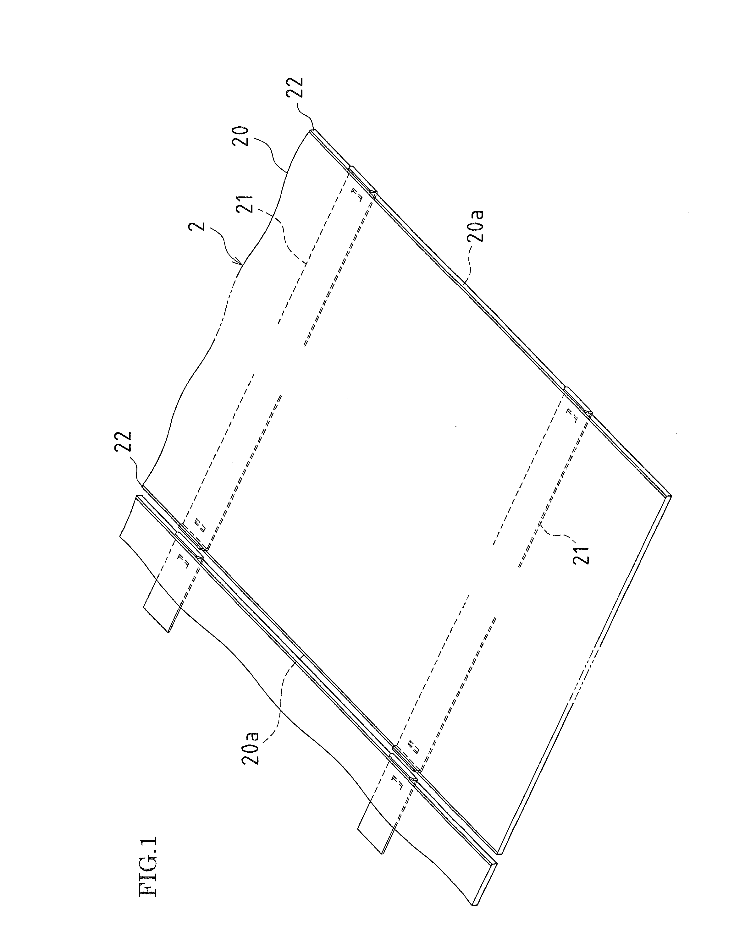
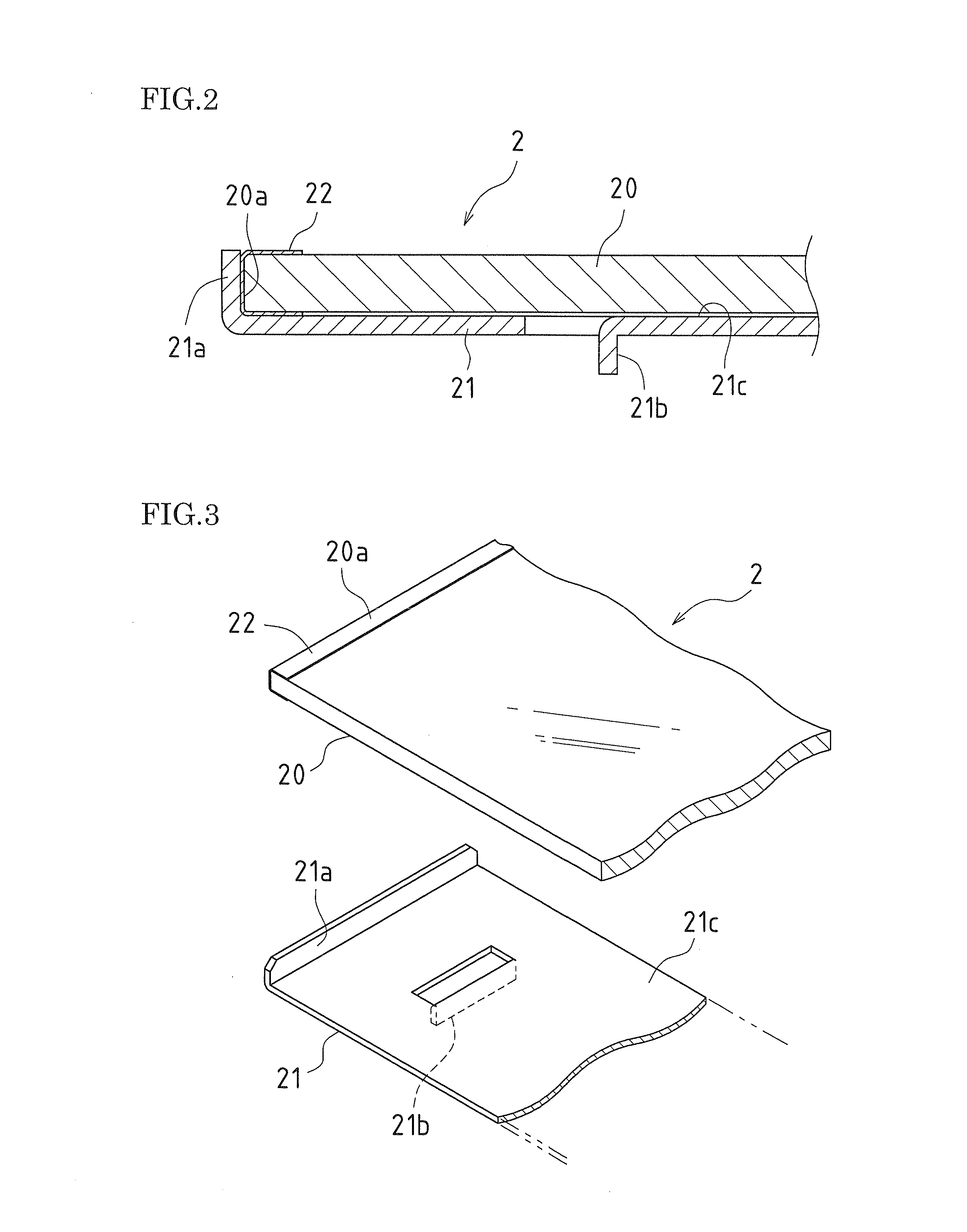
[0062]FIG. 1 is a perspective view of a solar cell module according to the present invention. FIG. 2 is a partially enlarged cross-sectional view of the solar cell module according to an embodiment of the present invention. FIG. 3 is a partially enlarged and exploded perspective view of the solar cell module according to an embodiment of the present invention.

[0063]As clearly seen from FIGS. 1 to 3, a solar cell module 2 includes a solar cell panel 20 and two reinforcing bars 21. The two reinforcing bars 21 are disposed to laterally cross the solar cell panel 20 and superimposed and adhered on the rear surface of the solar cell panel 20.

[0064]The solar cell panel 20 includes a transparent substrate such as of glass on which a thin-film semiconductor layer that carries out photoelectric conversion, an electrode film that transmits electric power, and the like are layered. The thin-film semiconductor layer, the electrode film, and the like are covered with a rear surface protective la...

second embodiment

[0113]Next, a solar cell module according to the present invention will be described. FIG. 22 is a perspective view of a solar cell module according to this embodiment. FIG. 23 is a partially enlarged cross-sectional view of the solar cell module according to this embodiment. FIG. 24 is a partially enlarged and exploded perspective view of the solar cell module according to this embodiment.

[0114]As clearly seen from FIGS. 22 to 24, a solar cell module 2A includes a solar cell panel 20 and two reinforcing bars 21A. The two reinforcing bars 21A are disposed to laterally cross the solar cell panel 20 and superimposed and adhered on the rear surface of the solar cell panel 20.

[0115]The solar cell panel 20 includes a transparent substrate such as of glass on which a thin-film semiconductor layer, an electrode film, and the like are layered. The thin-film semiconductor layer, the electrode film, and the like are covered with a rear surface protective layer and the like. To each of opposin...


PUM


Abstract

To protect a solar cell panel and facilitate the attachment of the solar cell panel on a roof and the like. A solar cell module 2 includes a solar cell panel 20 and two reinforcing bars 21 that laterally cross the solar cell panel 20 and that are disposed and adhered on the rear surface of the solar cell panel 20. Each of the reinforcing bars 21 is in the form of a rectangular and flat plate having a length that is approximately the same as the lateral width of the solar cell panel 20. Both end portions of each reinforcing bar 21 are bent upwardly to form hooking portions 21a of each reinforcing bar 21. U-shaped notches are formed adjacent to both ends of each reinforcing bar 21, and the U-shaped parts are bent downwardly to form protruding engagement portions 21b. An example of the reinforcing bar 21 is made of a steel plate that is cut, bent, and subjected to plating.

Description

TECHNICAL FIELD[0001]The present invention relates to a solar cell module, a solar cell attachment stand, and a photovoltaic power generating system.DESCRIPTION OF THE BACKGROUND ART[0002]In conventional systems of this kind, a solar cell module in which four sides of a solar cell panel are held with a frame member has been used. This is because the solar cell panel is mainly made of a substrate made of glass and the like, and thus the solar cell panel itself is brittle. In order to make up for this disadvantage, it is effective to protect the four sides of the solar cell panel with the frame member.[0003]Also, since it is difficult to directly install the solar cell panel having such brittleness on a roof and the like, it is preferable that the solar cell panel be held with the frame member, and the frame member be installed and secured on the roof and the like.[0004]For example, patent document 1 discloses a system in which the four sides of a solar cell panel are held with a fram...

Claims


Application Information

Patent Timeline
Patent Type & Authority Applications(United States)
IPC IPC(8): H01L31/048H01L23/12
CPCY02B10/12Y02B10/20Y02E10/47Y02E10/50H02S20/00F24S25/636F24S2080/09F24S2025/804F24S2025/016F24S25/10H02S20/23Y02B10/10
Inventor SAGAYAMA, KENICHI
Owner SHARP KK
Learn More