Case for Electronic Tablet

a tablet and electronic technology, applied in the field of electronic tablet accessories, can solve the problems of more likely accidental drop, hit, scratch, and device damage, and achieve the effect of reducing loss, adding functionality and usability

Active Publication Date: 2012-02-16
VINCI BRANDS LLC
View PDF1 Cites 120 Cited by
  • Summary
  • Abstract
  • Description
  • Claims
  • Application Information

AI Technical Summary

Benefits of technology

[0007]A case incorporates a built-in stand for the device which the case houses. The built-in stand allows using the case as a stand without needing to carry a separate standalone stand device. By incorporating the stand as part of the case, the case has additional functionality and usability. Since the stand is built-in or integrated, the stand will be available wherever the case is and is harder to lose than having a separate stand.

Problems solved by technology

As such, these devices are more vulnerable to damage as compared to nonportable devices.
These devices are more likely to be accidentally dropped, hit, or scratched.
However, other types of damage may ruin or limit the functionality of the device.
Often these devices contain sensitive and fragile components (e.g., screen, camera lens, flash, processors, accelerometers, and sensors).
Accidentally dropping the device could render various features unusable.

Method used


Image

  • Case for Electronic Tablet
  • Case for Electronic Tablet
  • Case for Electronic Tablet

Examples


first embodiment

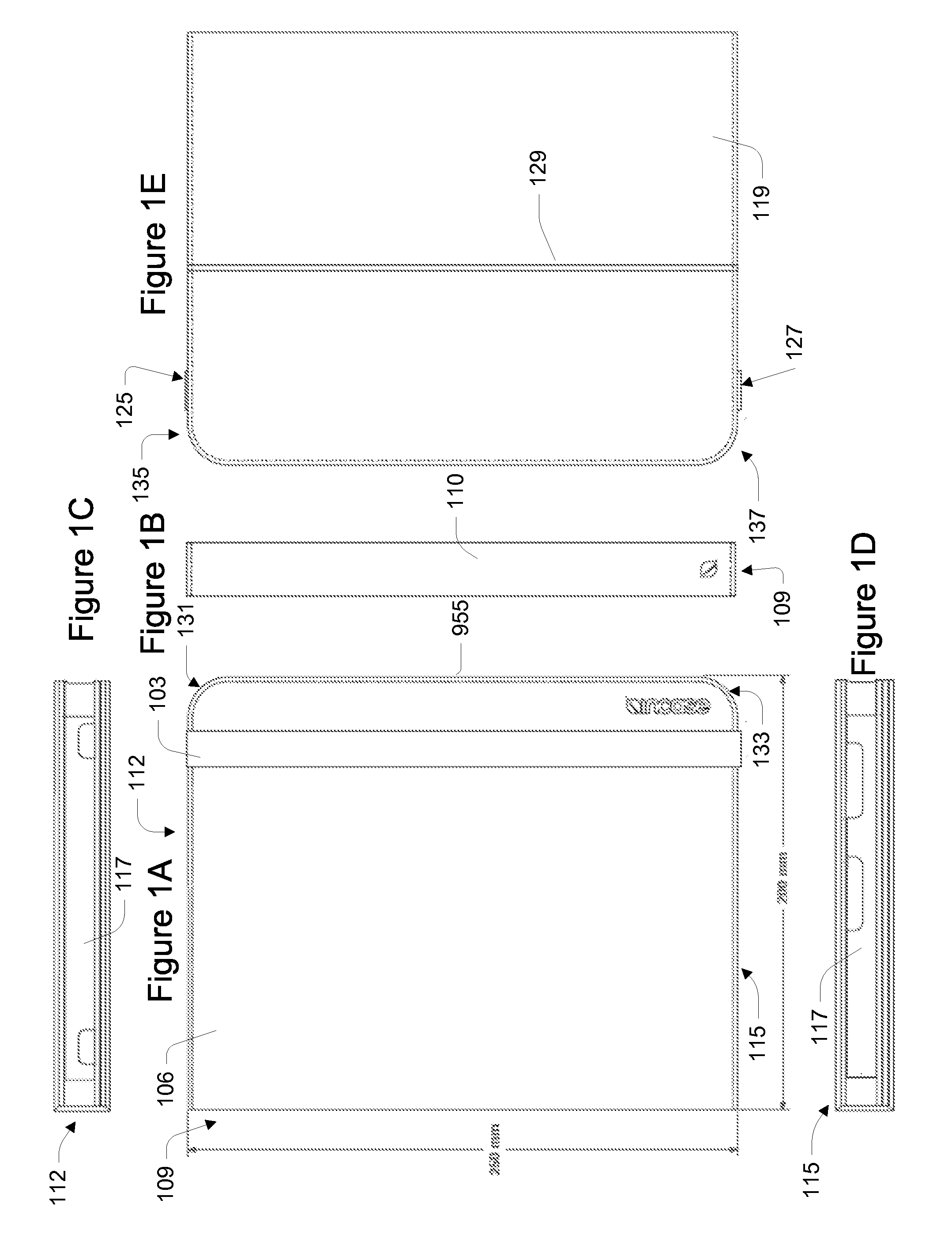
[0169]FIG. 10 shows a back perspective view of a closed case. FIG. 11 shows a front perspective view of the closed case. This case includes a thermoplastic polyurethane-polycarbonate (TPU-PC) frame construction. The case has an edge welded outer cover and can provide functionality and features similar to the case described above. This construction allows for a thin, light, and durable design. Some features of the case include full hard shell protection, access to all ports, over-molded power and volume buttons, display protection, three different viewing angles, a working angle, and a rubber band closing mechanism.

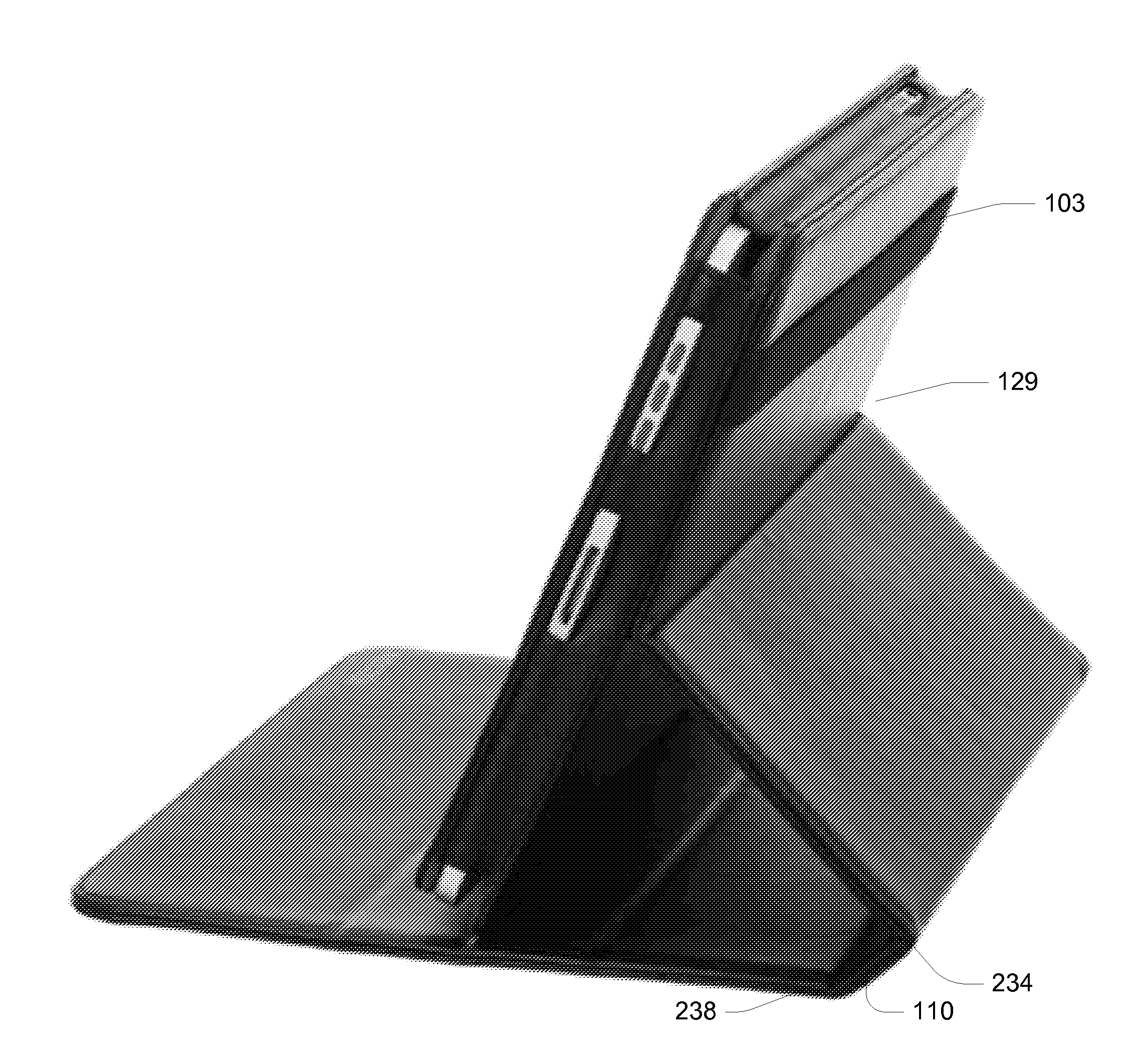
[0170]FIG. 12-14 show the case being used a stand for the electronic device. FIG. 12 shows how a frame 1302 of the case can be adjusted to be placed into one of the three viewing angles. FIG. 13 shows a front perspective view of the case in one of the viewing angles.

[0171]The frame has a bezel and front opening defined by the bezel through which the screen of the electroni...

second embodiment

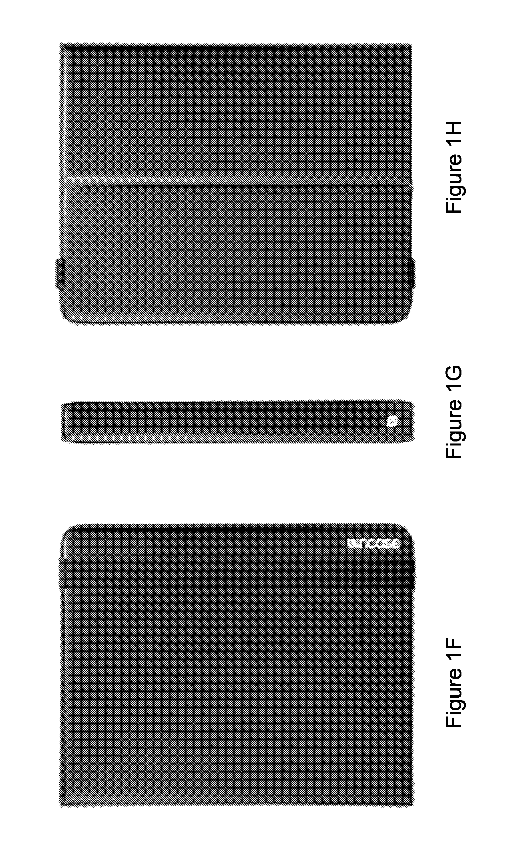
[0190]FIG. 30 shows an outside view of the case. FIGS. 31-34 show various side, bottom, and top views of the case. Referring to FIG. 30, this case is similar to the case described above. However, outer cover 3005 of this case is made of a thermoplastic polyurethane material. The cover is formed from a thermoplastic polyurethane mold. In this implementation, unlike for case the FIGS. 10-29 where the cover is a composite material (e.g., thermoplastic polyurethane and polycarbonate), the outer cover is made of a single type of material—thermoplastic polyurethane. In an alternative implementation, the single type of material is an thermoplastic elastomer.

[0191]The case includes hinges 3010, 3015, and 3020, and a rubber strap 3025. An outside surface of the front flap can include a debossed logo.

[0192]FIG. 31 shows a top view of the case. FIG. 32 shows a bottom view of the case. FIG. 33 shows a side view of the frame and over-molded buttons 3305. FIG. 34 shows a side view of the spine pa...


PUM

PropertyMeasurementUnit
lengthaaaaaaaaaa
lengthaaaaaaaaaa
viewing angleaaaaaaaaaa

Abstract

A case incorporates a built-in stand for the electronic device which the case houses.

Description

CROSS-REFERENCE TO RELATED APPLICATIONS[0001]This application is a continuation of U.S. patent application Ser. No. 12 / 892,736, filed Sep. 28, 2010, which claims the benefit of U.S. provisional application 61 / 372,450, filed Aug. 10, 2010, and 61 / 382,472, filed Sep. 13, 2010, which are incorporated by reference along with all other references cited in this application.BACKGROUND OF THE INVENTION[0002]This invention relates to accessories for electronic devices and more specifically to cases for portable electronic devices and electronic tablets.[0003]With each new generation, portable electronic devices provide greater functionality and have more capabilities. These portable electronic devices allow people to play and record music, send and receive e-mail, send text messages, browse Web pages, make phone calls, play and record video, take and view pictures, edit documents, and much more. These devices continue to revolutionize the way people interact, learn, connect with other people...

Claims


Application Information

Patent Timeline
Patent Type & Authority Applications(United States)
IPC IPC(8): H05K5/03B31B1/90B31B29/26
CPCA45C5/02G06F1/1626A45C13/005A45C2011/003A45C2013/025A45C2200/15G06F2200/1633H04M1/04G06F1/1628B65D85/00H05K13/00B65B5/04Y10T29/49002Y10T29/49826A45C11/00
Inventor DIEBEL, MARKUSHONG, HYUN
Owner VINCI BRANDS LLC
Why Eureka
Try Eureka