Hollow target assembly

a target body and hollow technology, applied in the field of hollow target assembly, can solve the problems of high cost of metals having low melting point, inconvenient deposition of large area, and cracks between the target body and the support tube, so as to improve the drawbacks of high cost, poor contact, and complicated process

Inactive Publication Date: 2012-02-16
SOLAR APPLIED MATERIALS TECHNOLOGY CORPORATION
View PDF4 Cites 0 Cited by
  • Summary
  • Abstract
  • Description
  • Claims
  • Application Information

AI Technical Summary

Benefits of technology

[0007]The purpose of the present invention is to provide a hollow target assembly to improve the drawbacks of high cost, complicated process, bad contact between the target body and the support tube, and bad quality of the film deposited by the target material.

Problems solved by technology

The sputtering efficiency of conventional plane target is only from 15% to 40%, which makes it unsuitable for large area deposition.
However, the cost for the metals having low melting point is too high, and the inside surface of the target body and the outside surface of the support tube need further metallization.
Furthermore, during the deposition and cooling processes, cracks may generate between the target body and the support tube because they have different heat expansion coefficient.
However, the equipment for heat treatment is expensive and will accordingly increase the production cost.
Further, cracks and peelings may occur when the thermal expansion coefficient difference between the support tube and the target body is too large and causes too much stress on the meshing part.
When using casting technique to form the target body, the high casting temperature and long time cooling cause the density of the target body to decrease and the microstructure of the target body not uniform so the quality of the deposited film is not good.
If not enough elastic elements are used, the friction provided by the elastic elements may not be enough to prevent the target body from moving.
How to put enough elastic elements into the gap between the support tube and the target body is a very complicated technique.

Method used


Image

  • Hollow target assembly
  • Hollow target assembly
  • Hollow target assembly

Examples


example

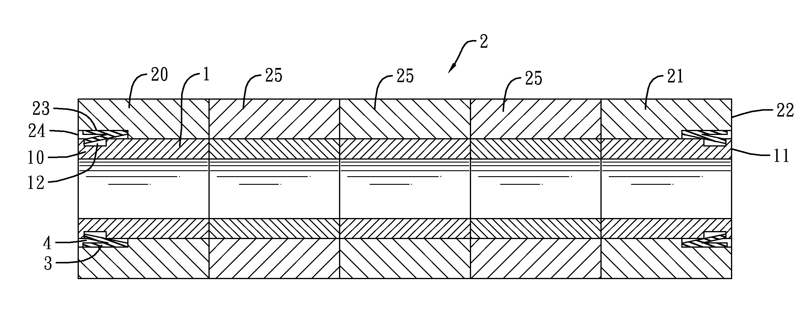
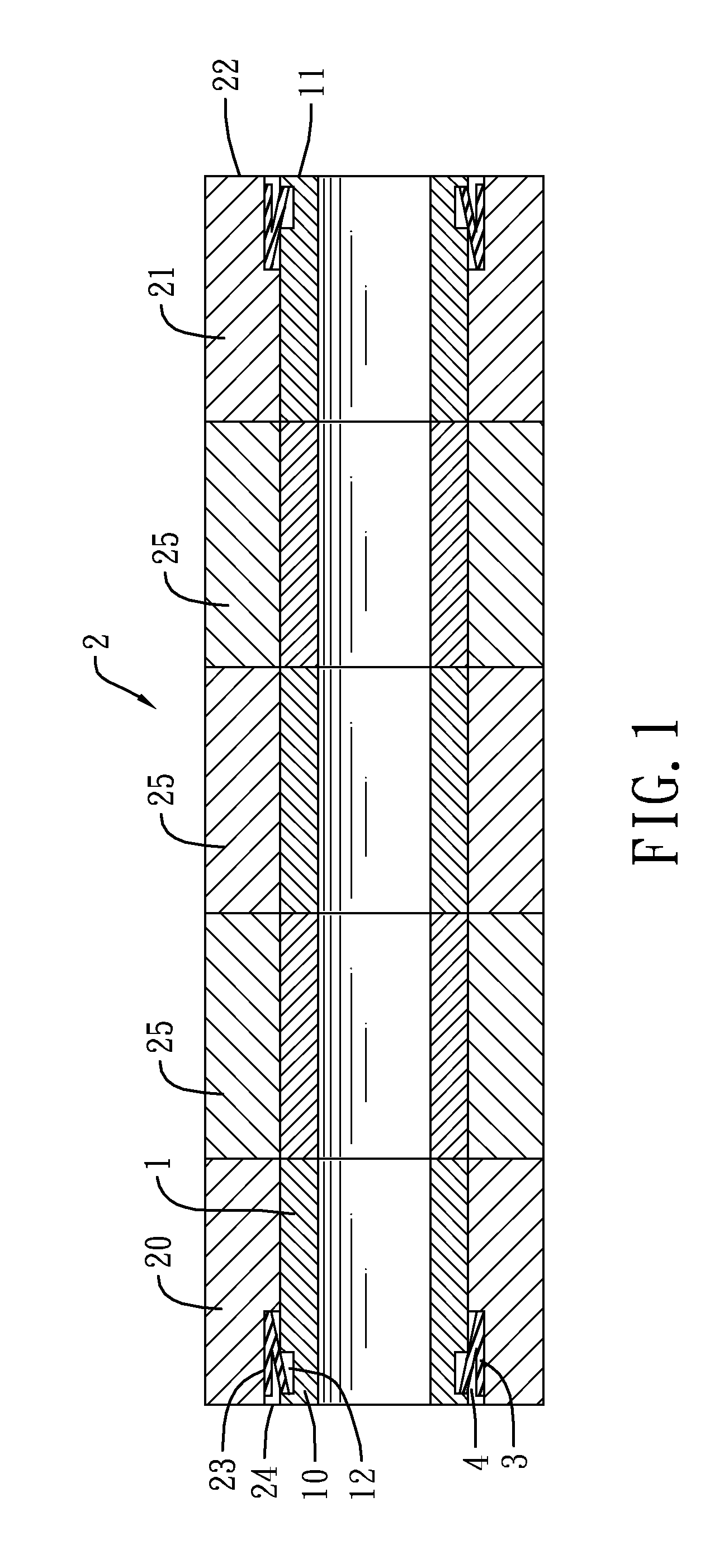
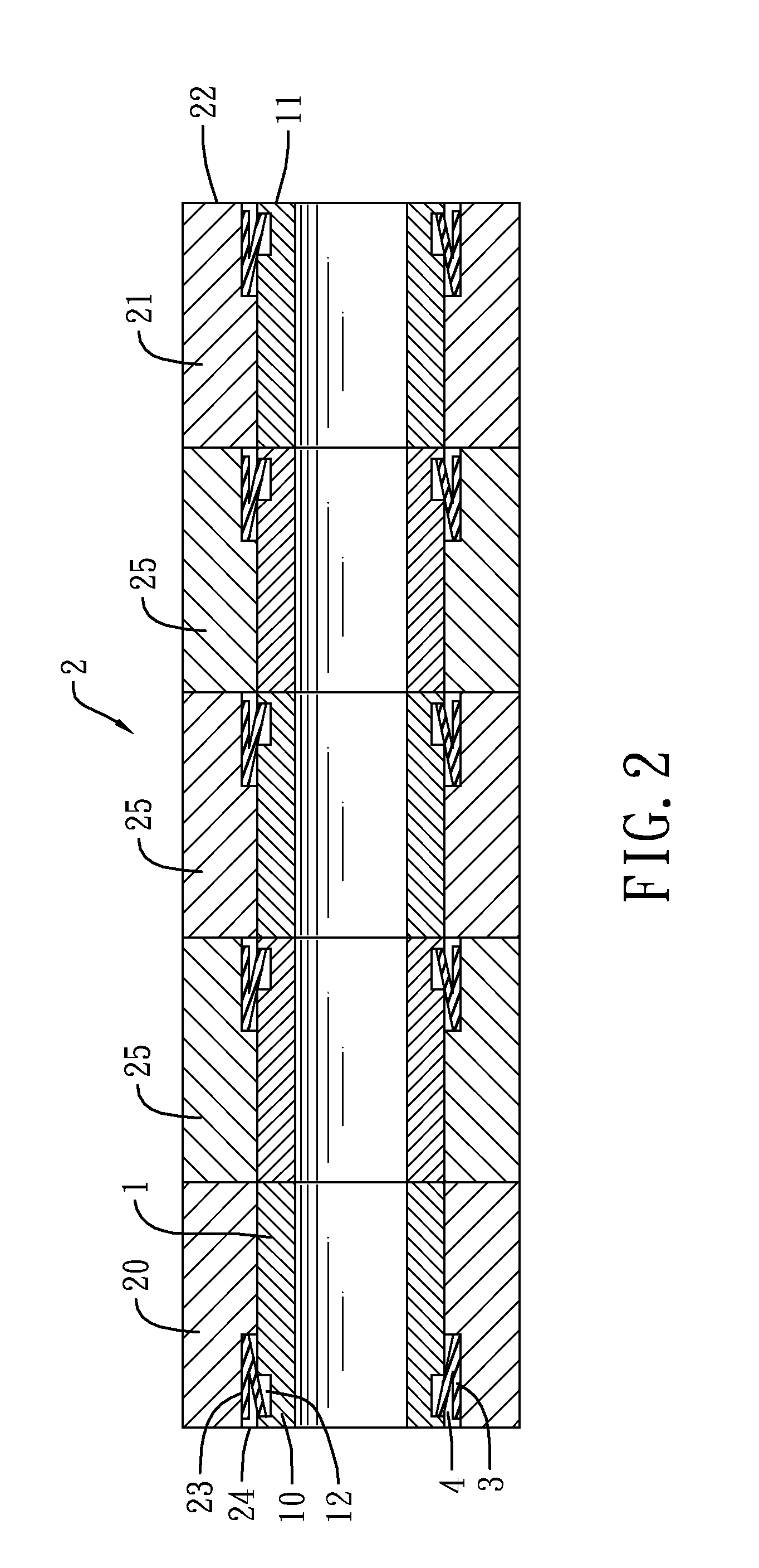
[0041]The aluminum zinc oxide is chosen as a sputtering material and forms a target body 2. The target body 2 contains one first hollow target material 20, one second hollow target material 21 and three third hollow target material 25. The outer diameter and the inner diameter of the three kinds of the hollow target materials are respectively 160 mm and 133 mm. Each length in the axial direction of the target materials is 280 mm so the total length of the target body 2 is 1400 mm. Grooves 23 are made as a continuous loop by machining in the inner surface of the first hollow target material 20 and the second hollow target material from an end 22 of said target materials with 10 mm depth in the axial direction and 2 mm in the circumferential direction. The support tube 1 is made by stainless SUS304. The outer diameter and inner diameter of the lined pipe 1 are respectively 132.5 mm and 125 mm. The length of the support tube 1 is 1450 mm. The outer diameter of the support tube 1 is 0.5...


PUM

PropertyMeasurementUnit
inner diameteraaaaaaaaaa
lengthaaaaaaaaaa

Abstract

A hollow target assembly has a support tube, a target body and a plurality of elastic elements. The target body includes a plurality of hollow target materials and they pass through the support tube sequentially and locate at the outer surface of the support tube. By the grooves formed and extended from an end of the inside wall of the hollow target material and the corresponding concaves formed at the outside wall of the support tube, the elastic elements can lean and be positioned in the space generated by the grooves and corresponding concaves. Therefore, the target body and the support tube are brought together closely by these elastic elements in a simple and a low-cost way.

Description

BACKGROUND OF THE INVENTION[0001]1. Field of the Invention[0002]The present invention relates to a sputtering target assembly, especially a hollow target assembly using elastic elements to provide good adhesiveness between the support tube and the target body.[0003]2. Description of the Prior Arts[0004]The sputtering efficiency of conventional plane target is only from 15% to 40%, which makes it unsuitable for large area deposition. To reduce cost, the rotating target is widely used in large area deposition in place of the plane target because the sputtering efficiency of the rotating target can reach 70% to 90%.[0005]A rotating target normally comprises a target body and a support tube. The target body covers the outer circumferential surface of the support tube. The target body will generate large amount of heat during the deposition, and the heat needs to be conducted to the cooling medium via the support tube. Therefore, sufficient contact area between the support tube and the t...

Claims


Application Information

Patent Timeline
Patent Type & Authority Applications(United States)
IPC IPC(8): C23C14/34
CPCC23C14/3407H01J37/3417H01J37/342H01J37/3429
Inventor WU, CHUNG-HANLAI, KUAN-TINGWANG, TZU-WEN
Owner SOLAR APPLIED MATERIALS TECHNOLOGY CORPORATION
Why Eureka
Try Eureka