

Device and method for electromechanically-assisted roller burnishing
- Summary
- Abstract
- Description
- Claims
- Application Information
AI Technical Summary
Benefits of technology
Problems solved by technology
Method used
Image

Examples
Embodiment Construction
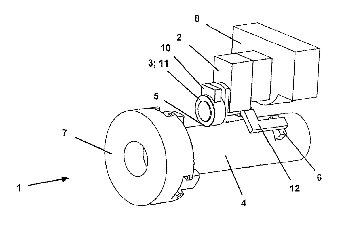
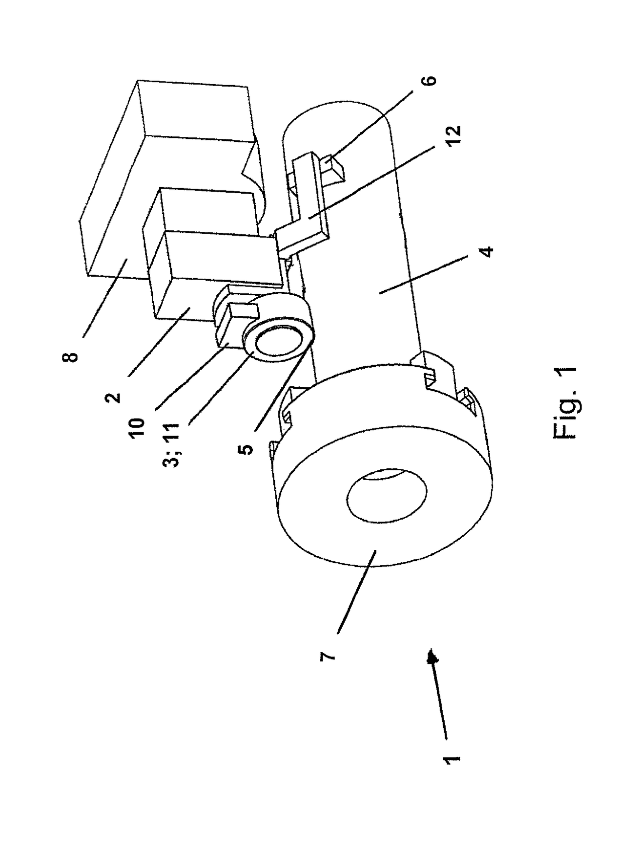
[0031]FIG. 1 shows a device according to the invention, for the electromechanically assisted roller burnishing.
[0032]The construction of the device shown in FIG. 1 is firstly that of a classical lathe or a corresponding roller burnishing device. A workpiece 4 (an elongate turned part) can be chucked into a first receiver 7. The receiver can be adjusted by way of a suitable clamping for workpieces of a different diameter, in order to anchor these in the receiver in a rotationally fixed manner and then to achieve a controlled rotational movement about the longitudinal axis of the workpiece 4.
[0033]A roller burnishing tool 2 is clamped in a second receiver, a tool receiver 8. This tool receiver is designed such that a lathe tool or likewise can also be clamped here.
[0034]The roller burnishing tool 2 is dealt with in a detailed manner hereinafter, wherein this tool can be completely (i.e. including a dog 12 and the second electrical contact element 6) retrofitted, i.e. can be clamped in...
PUM
| Property | Measurement | Unit |
|---|---|---|
| Temperature | aaaaa | aaaaa |
| Length | aaaaa | aaaaa |
| Strength | aaaaa | aaaaa |
Abstract
Description
Claims
Application Information