
Motor with impedance balanced winding

Inactive Publication Date: 2012-02-23
NIDEC MOTOR CORP
View PDF4 Cites 8 Cited by
  • Summary
  • Abstract
  • Description
  • Claims
  • Application Information

AI Technical Summary

Benefits of technology

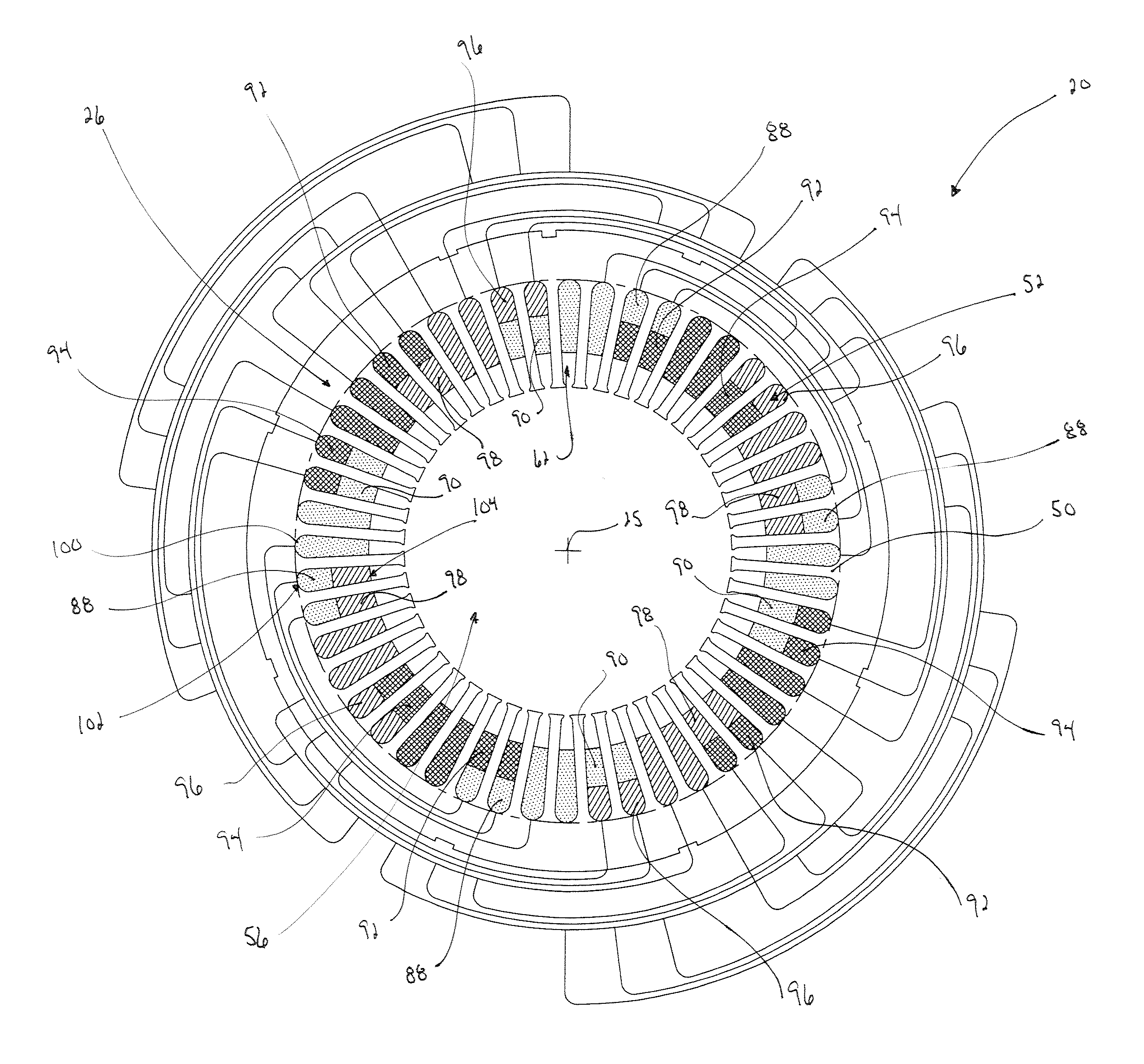
[0010]According to an aspect of the present invention, an inventive machine-insertion technique has been developed that more closely resembles the structure provided by lap winding in a three-phase electric motor. The new insertion technique yields a motor with more balanced impedance, increased efficiency, and provides for mechanized insertion of phase winding portions for high production capabilities. The structure from the inventive insertion technique also results in better thermal performance of the motor, since at least a portion of each phase winding is disposed along both radially outer and radially inner portions of the total winding. Such an arrangement of the phase windings more directly exposes at least a portion of each phase winding to a cooling system for the phase windings, such as a cooling oil spray.

Problems solved by technology

Lap winding is known to be generally effective in some ways, but the coils must be manually inserted and manipulated by hand This is a time-consuming and labor-intensive process that can be detrimental to large-scale production.
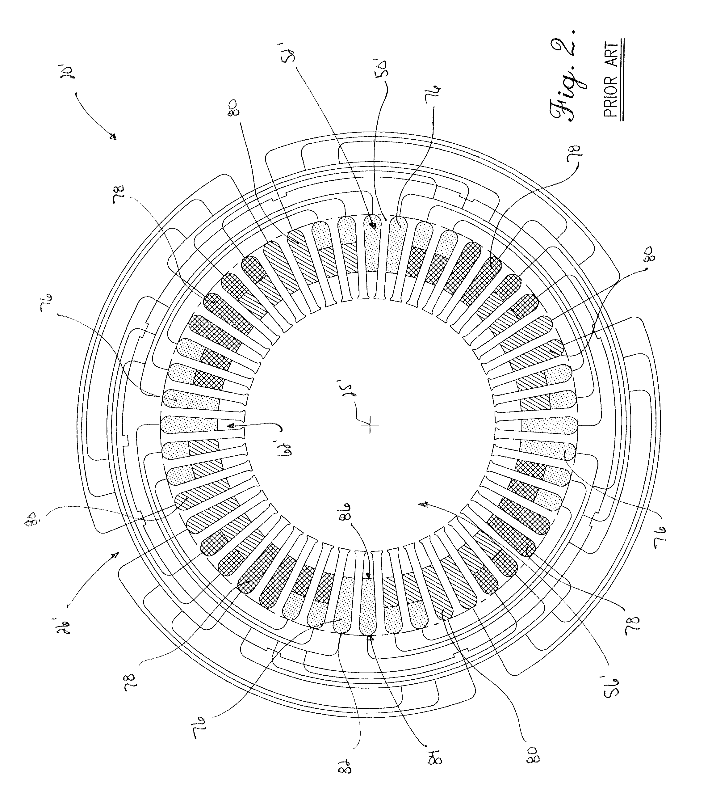
While known machine-insertion techniques have been satisfactory in some respects, notably in that increased production can be realized, such machine-insertion techniques have also presented drawbacks in the structure of the total winding.
For example, the variance in axial disposition between the phase windings created by sequential order insertion results in an impedance imbalance between the phases across an air gap between the rotor and the stator.
Such an impedance imbalance detrimentally impacts overall efficiency of the motor and can create an inability to meet high efficiency demands.
In addition, the relative radially outer disposition of the first-inserted A-phase compared to the relative radially inner disposition of the last-inserted C-phase presents drawbacks in cooling performance.
When the radially inner C-phase runs hotter, this phase ages faster and may create hot spots that can lead to premature failure of the motor, it may operate at a temperature over the induction class limit, and it may exhibit increased resistance within the phase and lead to further impedance imbalance.
Even with high volume production requirements, it remains undesirable to suffer an efficiency loss and a thermal performance detriment of known machine-insertion methods, especially when trying to meet high efficiency demands.

Method used


Image

  • Motor with impedance balanced winding
  • Motor with impedance balanced winding
  • Motor with impedance balanced winding

Examples


Embodiment Construction

[0029]The present invention is susceptible of embodiment in many different forms. While the drawings illustrate, and the specification describes, certain preferred embodiments of the invention, it is to be understood that such disclosure is by way of example only. There is no intent to limit the principles of the present invention to the particular disclosed embodiments.

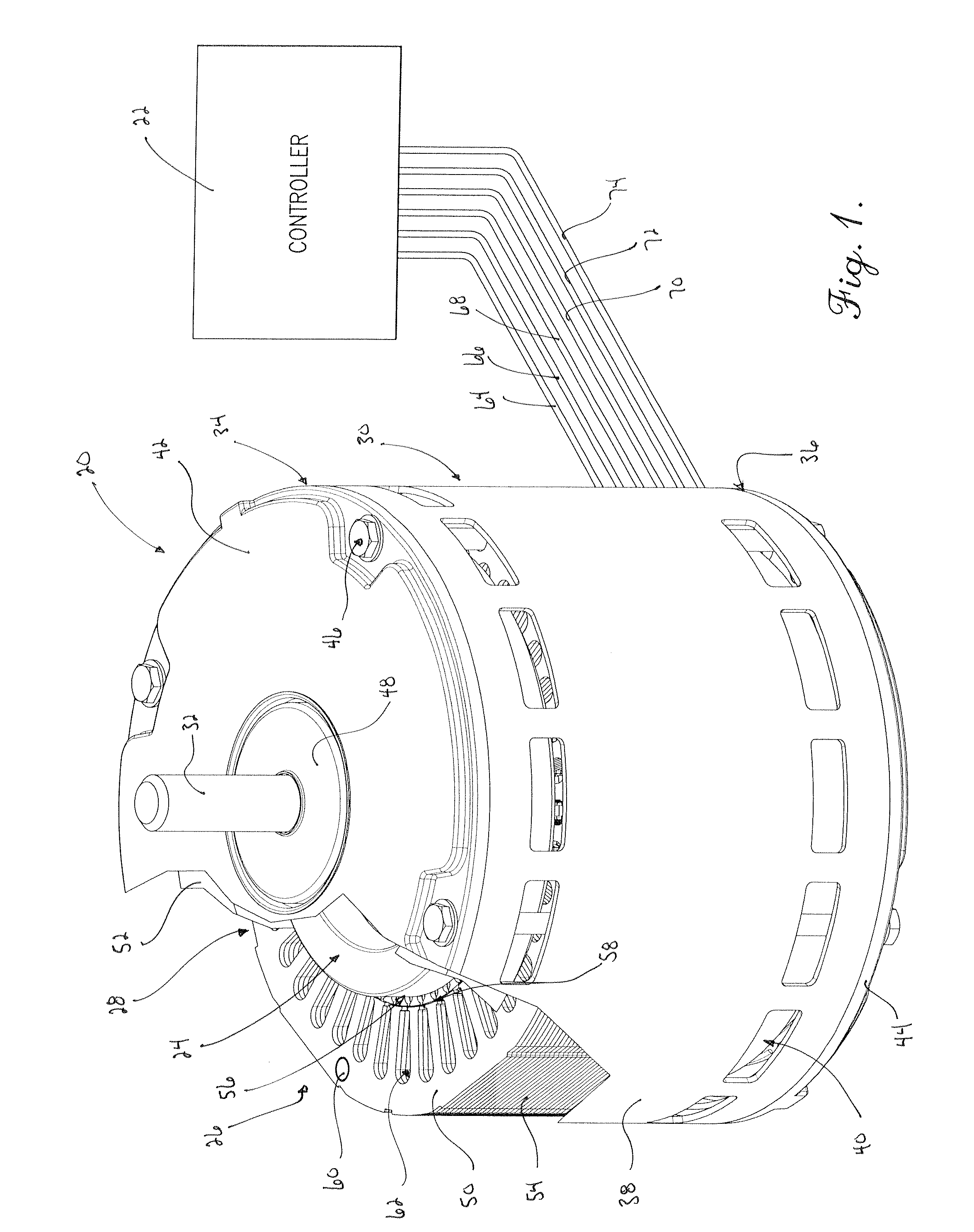
[0030]With initial reference to FIG. 1, a three-phase, electric induction motor assembly 20 constructed in accordance with the principles of an embodiment of the present invention is depicted for use in various applications. While the motor assembly 20 is useful in various applications, the illustrated embodiment has particular utility when the motor assembly 20 is configured to power industrial machinery. More specifically, the motor assembly 20 may include a digital controller 22, and is notably advantageous when the motor assembly 20 is configured to power a drive system in a track-type tractor (not shown).

[0031]I...


PUM

PropertyMeasurementUnit
Electrical resistanceaaaaaaaaaa
Mechanical propertiesaaaaaaaaaa
Electric impedanceaaaaaaaaaa

Abstract

A three-phase electric motor assembly is configured to include phase windings that are substantially equally distributed between radially inner portions and radially outer portions within axial slots of a stator core. At least two of the phase windings each include radial inner portions within selected slots and radial outer portions within other slots, such that each of the radial inner portions is positioned within a slot radially inward from the radial outer portion of another of the phase windings, and each of the radial outer portions is positioned within a slot radially outward from the radial inner portion of another of the phase windings. The motor assembly provides balanced impedance between the phase windings to minimize losses attributed to inter-phase circulating currents, increasing overall motor efficiency. The arrangement of the phase windings configures the winding for more direct exposure of at least a part of each phase winding to a cooling system for enhanced heat rejection from end coils. Methods for inserting partial phase windings that can be mechanically executed are also provided.

Description

BACKGROUND OF THE INVENTION[0001]1. Field of the Invention[0002]The present invention relates generally to a three-phase, electric motor assembly. More specifically, aspects of the present invention concern a three-phase, electric motor assembly that includes phase winding portions that are disposed within a stator core assembly to balance impedance, increase motor efficiency, and provide for mechanized insertion of the phase winding portions.[0003]2. Discussion of the Prior Art[0004]Those of ordinary skill in the art will appreciate that three-phase electric motors are known to be generally effective and are commonly used in a variety of industrial applications. For example, three-phase electric motors may be used to power industrial machinery, such as a drive system in a track-type tractor, among other things. Three-phase electric motors include at least three distinct phase windings, commonly referred to, and readily understood by one of ordinary skill in the art, as A-phase, B-p...

Claims


Application Information

Patent Timeline
IPC IPC(8): H02K3/28H02K15/085
CPCH02K3/28Y10T29/49009H02K15/085
Inventor WOLFINGTON, DANIEL R.BOMAR, JOEY M.MCCLOSKEY, SEAN P.
Owner NIDEC MOTOR CORP
Learn More