Power amplifier assembly comprising suspended strip lines

a technology of power amplifiers and strips, applied in amplifiers, amplifiers with semiconductor devices/discharge tubes, waveguides, etc., can solve the problems of reducing the overall efficiency of the transmitter, and significantly contributing to the power consumption of dc (direct current). cost

Active Publication Date: 2014-04-17
TELEFON AB LM ERICSSON (PUBL)
View PDF7 Cites 2 Cited by
  • Summary
  • Abstract
  • Description
  • Claims
  • Application Information

AI Technical Summary

Benefits of technology

[0009]By positioning the conductor arrangement in the recess, several advantages are achieved. Firstly, impedance is more predictable, whereby the control of the impedance increased. Secondly, electrical and mechanical isolation between various parts of the circuitry, such as the amplifier branches, is improved. It is to be noted that the phrase ‘suspended conductor’ is also denoted ‘suspended line’ and the two terms can be exchanged for each other.
[0011]The recess of the grounding structure may face the circuit board. In this way, the suspended conductors are essentially surrounded by the circuit board and the grounding structure. This surrounding grounding around the suspended conductors reduces susceptibility to electromagnetic interference and also reducing losses.
[0015]The first section of the conductor arrangement may be in galvanic contact with the plurality of input connection points; the second section of the conductor arrangement may be in galvanic contact with the output connection point; and there may be an overlap between the first section and the second section to provide an electromagnetic coupling between the first section and the second section. This makes the conductor arrangement provide DC blocking as part of within its structure, eliminating the need for capacitors for DC blocking, which reduces cost.

Problems solved by technology

Generally, components and signal tracks of the final parts of the radio signal chain contributes significantly to the DC (Direct Current) power consumption.
Microstrip transmission lines, surface mounted directional coupler and the isolator contribute to a loss of the transmitted signal and lower overall efficiency of the transmitter.
All features added after the final transmitter power amplifiers are especially costly, since any insertion loss at this point has great effect on the efficiency of the transmitter.
These losses reduce the performance of the system and can increase size due to space demanding physical cooling solutions.
Prior art solutions such as this improve upon DC / DC power consumed in the power amplifier, but may need large areas of combining networks at the output which also contributes to the loss after the power amplifier, and consequently decreases overall efficiency.
However, such a solution can be used only as a separate module because it is hard to integrate it with the standard PCB technology.
However, the combiner circuit is provided in a fragile structure and mechanical and electrical control of the suspended circuitry is limited.

Method used


Image

  • Power amplifier assembly comprising suspended strip lines
  • Power amplifier assembly comprising suspended strip lines
  • Power amplifier assembly comprising suspended strip lines

Examples


first embodiment

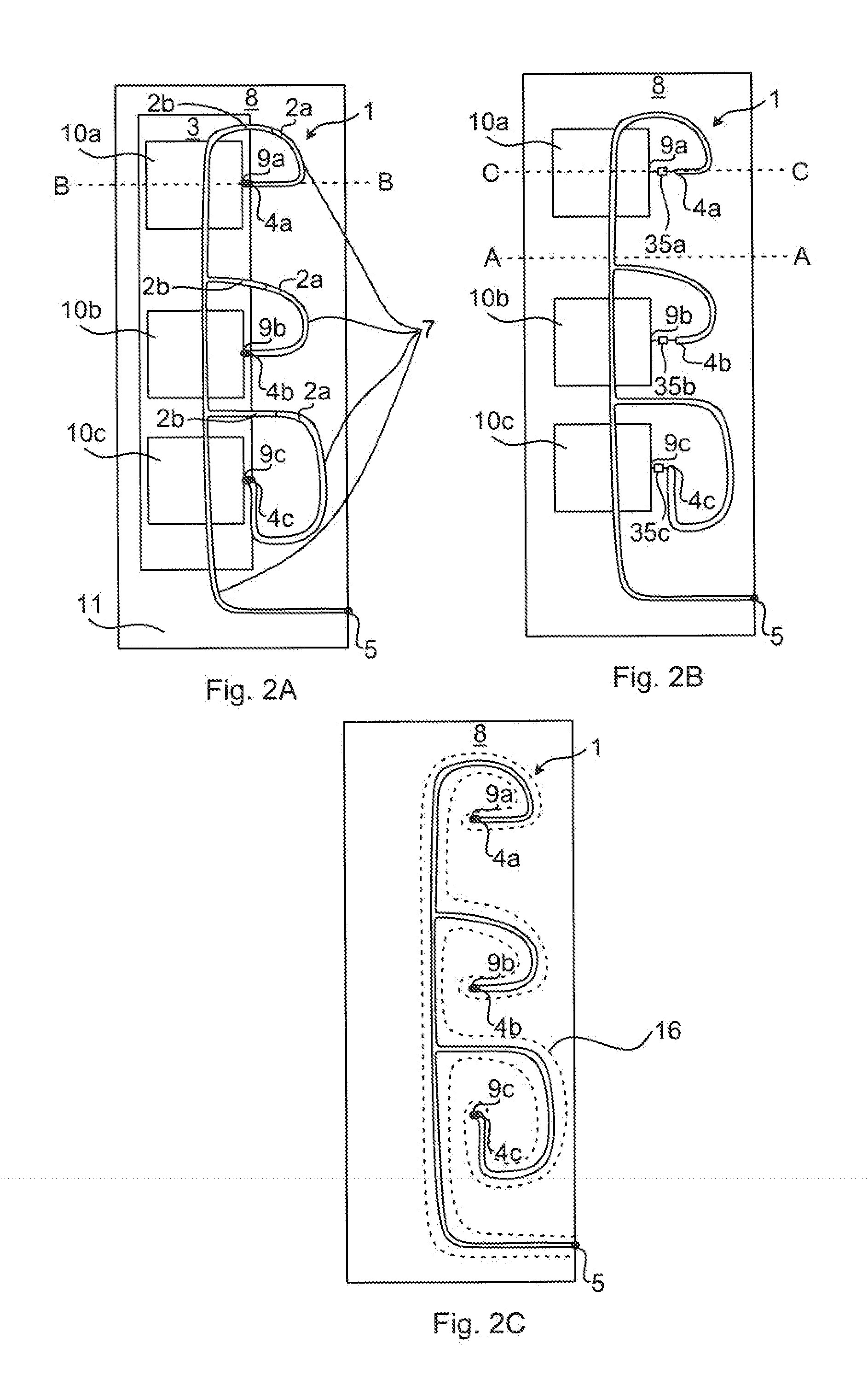
[0044]FIG. 4A is a cross sectional view along line C-C of FIG. 2B according to a Here the first drive amplifier 10a is shown as well as its output 9a. The corresponding input connection points 4a of the combining network 1 is also shown, with a galvanic connection to the conductor arrangement 7, as seen on the right in FIG. 4A. The conductor arrangement 7 loops around and is shown also on the left hand side of FIG. 4A. It is to be noted that the relative dimensions are not indicative of construction and the figure is only schematic. In this embodiment, a DC blocking device (not shown here), such as a capacitor, can be provided e.g. between the output 9a and the input connection point 4a.

second embodiment

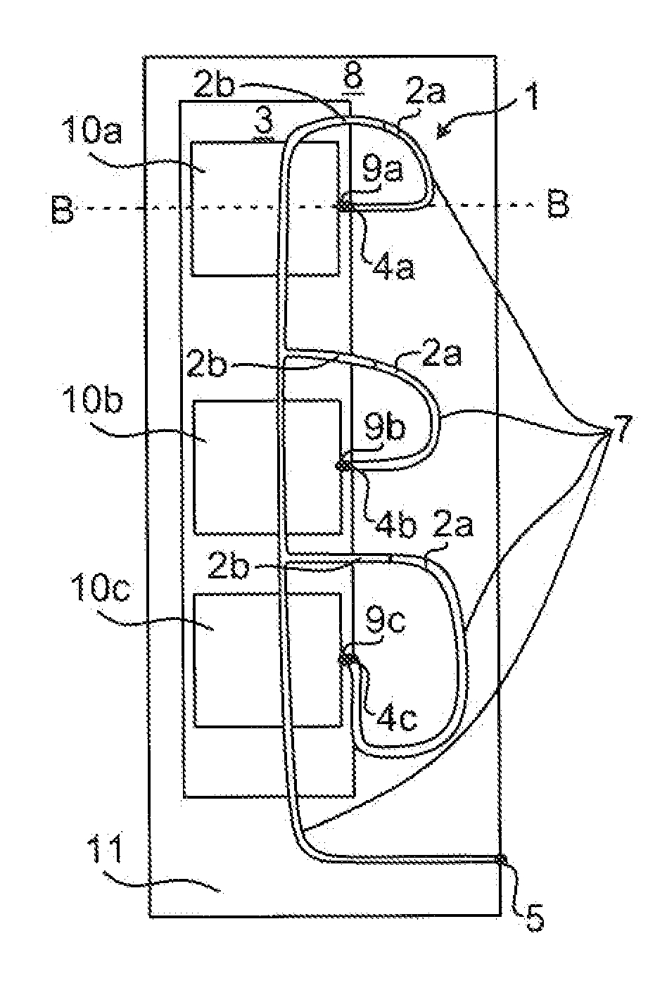
[0045]FIG. 4B is a cross sectional view along line B-B of FIG. 2A according to a The difference compared to FIG. 4A is that here, a first section 7a of the conductor arrangement 7 is arranged in a first layer 6a and a second section 7b is arranged in a second layer 6b. The distance between the first section 7a and the second section 7b is sufficiently short to provide sufficient electromagnetic coupling between the two sections. A further effect of this arrangement is that there is a DC block between the two sections, while still allowing RF signals to pass. This eliminates the need for a specific DC block device between the output of the drive amplifiers 10a-c and the combining network 1.

[0046]With combined reference to FIGS. 2A and 4B, the conductor arrangement 7 can be divided in a DC block part 2a and a main part 2b, where the DC block part 2a is arranged as shown in FIG. 4B. The DC block part 2a can be provided at a part of the conductor arrangement 7 which is closest to the i...


PUM


Abstract

It is presented a power amplifier assembly comprising; a radio frequency multi-order power amplifier comprising a circuit board; a grounding structure connected to the radio frequency multi-order power amplifier and comprising a recess; a combining network connected to a plurality of outputs of the radio frequency multi-order power amplifier. The combining network comprises: a plurality of input connection points, wherein each of the plurality of input connection points is connected to a respective output of the plurality of outputs of the radio frequency multi-order power amplifier; an output connection point; and a conductor arrangement comprising a plurality of conductive paths arranged between the plurality of input connection points and the output connection point; wherein at least one of the plurality of conductive paths is at least partly formed by a suspended conductor positioned in the recess of the grounding structure.

Description

TECHNICAL FIELD [0001]The present invention relates to a power amplifier assembly comprising a radio frequency multi-order power amplifier.BACKGROUND [0002]Transmitters in many radio-based telecommunications and broadcast systems are designed to transmit wide bandwidth modulated signals with the great power efficiency. Generally, components and signal tracks of the final parts of the radio signal chain contributes significantly to the DC (Direct Current) power consumption.[0003]A typical final amplification stage of the transmitter is made in multilayer microstrip / stripline-type printed circuit board (PCB) technology and contains an output matching network, a directional coupler and an isolator / circulator. The directional coupler picks up a small part of the transmitted signal back to a linearization / predistortion block. Microstrip transmission lines, surface mounted directional coupler and the isolator contribute to a loss of the transmitted signal and lower overall efficiency of t...

Claims


Application Information

Patent Timeline
Patent Type & Authority Applications(United States)
IPC IPC(8): H03F3/189H03F3/20
CPCH03F3/20H03F3/189H03F3/602H01P3/087H01P5/12H01P3/088H05K1/02
Inventor PLAHN, JOAKIMSAWICKI, ANDRZEJSCHOON, MARTIN
Owner TELEFON AB LM ERICSSON (PUBL)
Why Eureka
Try Eureka