

Optical image-capturing lens assembly
a technology of optical image and lens assembly, which is applied in the field of compact optical image capture lens assembly, can solve the problems of reducing the pixel size of sensors, reducing the standard for image quality, and reducing the degree of freedom in arranging the lens system, so as to reduce improve the resolution. , the effect of reducing the size of the lens assembly
- Summary
- Abstract
- Description
- Claims
- Application Information
AI Technical Summary
Benefits of technology
Problems solved by technology
Method used
Image

Examples
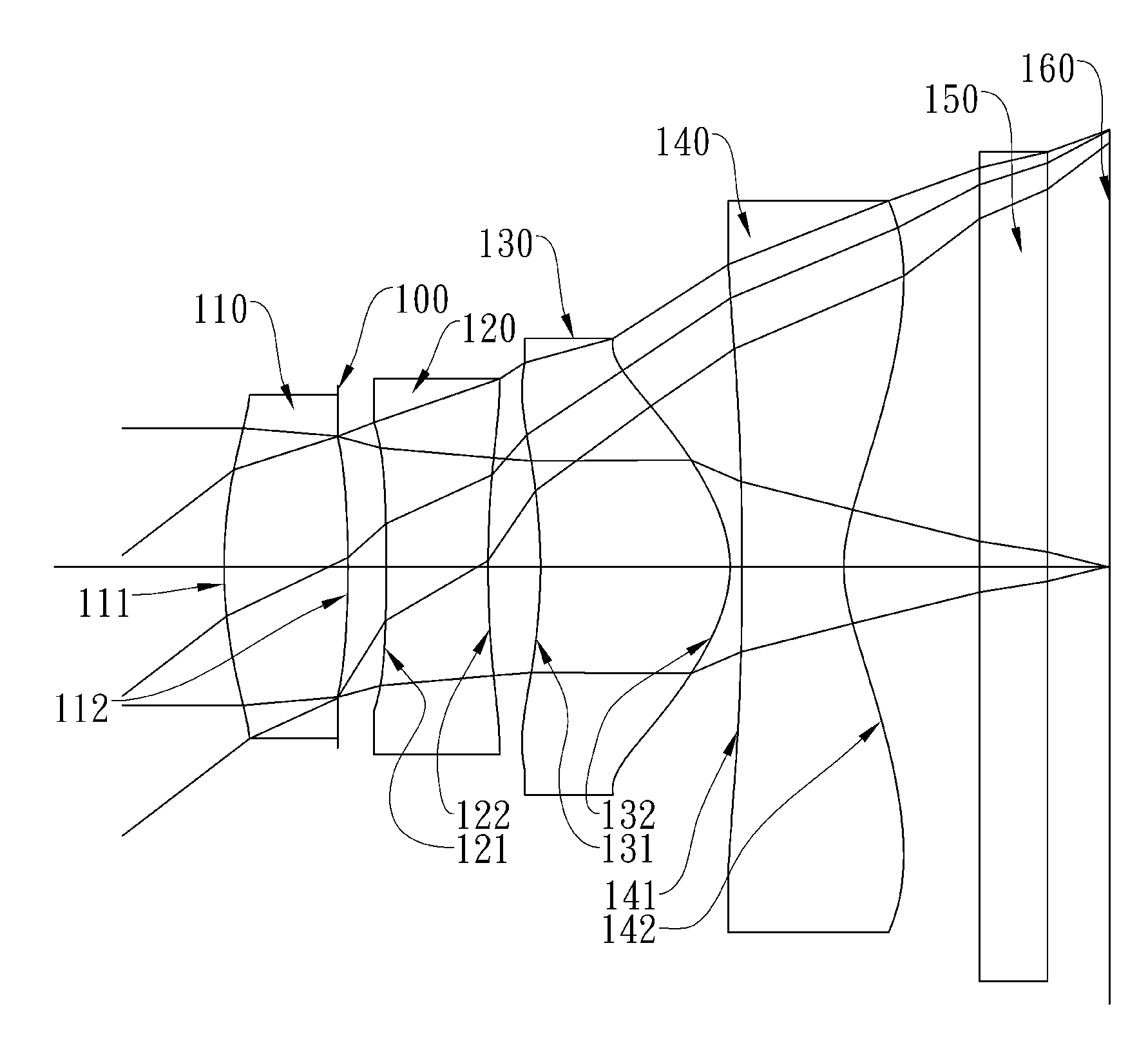
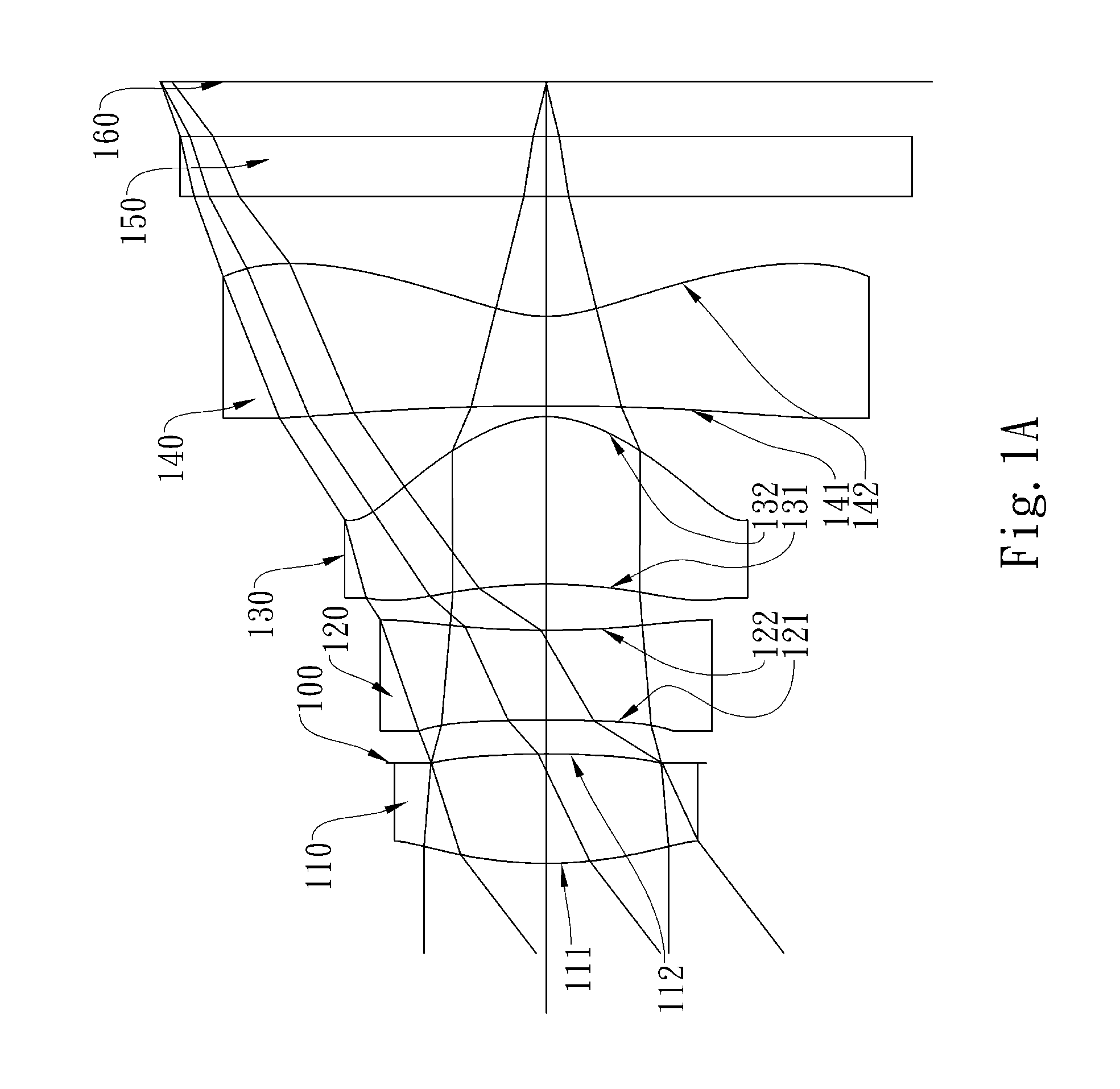
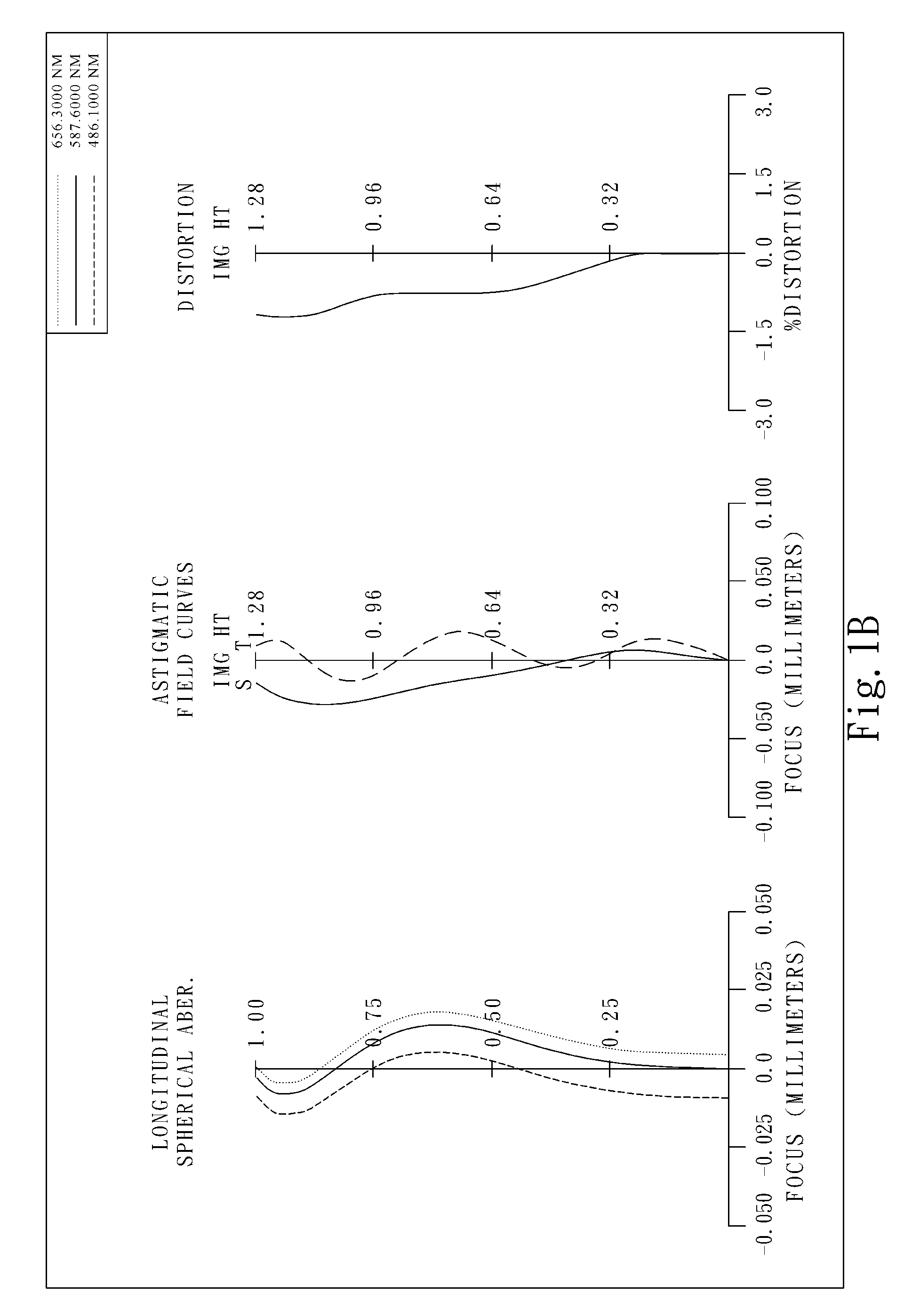
first embodiment
[0090]In the present optical image-capturing lens assembly, the focal length of the assembly is f, and it satisfies the relation: f=1.70 (mm).
[0091]In the first embodiment of the present optical image-capturing lens assembly, the f-number of the assembly is Fno, and it satisfies the relation: Fno=2.08.
[0092]In the first embodiment of the present optical image-capturing lens assembly, half of the maximum field of view of the assembly is HFOV, and it satisfies the relation: HFOV=37.4 (degrees).
[0093]In the first embodiment of the present optical image-capturing lens assembly, the Abbe number of the first lens element 110 is V1, the Abbe number of the second lens element 120 is V2, and they satisfy the relation: V1−V2=32.5.
[0094]In the first embodiment of the present optical image-capturing lens assembly, the radius of curvature of the image-side surface 142 of the fourth lens element 140 is R8, the focal length of the assembly is f, and they satisfy the relation: R8 / f=0.26.
[0095]In th...
second embodiment
[0105]In the present optical image-capturing lens assembly, the focal length of the assembly is f, and it satisfies the relation: f=1.70 (mm).
[0106]In the second embodiment of the present optical image-capturing lens assembly, the f-number of the assembly is Fno, and it satisfies the relation: Fno=2.08.
[0107]In the second embodiment of the present optical image-capturing lens assembly, half of the maximum field of view of the assembly is HFOV, and it satisfies the relation: HFOV=37.5 (degrees).
[0108]In the second embodiment of the present optical image-capturing lens assembly, the Abbe number of the first lens element 210 is V1, the Abbe number of the second lens element 220 is V2, and they satisfy the relation: V1−V2=32.5.
[0109]In the second embodiment of the present optical image-capturing lens assembly, the radius of curvature of the image-side surface 242 of the fourth lens element 240 is R8, the focal length of the assembly is f, and they satisfy the relation: R8 / f=0.26.
[0110]I...
third embodiment
[0120]In the present optical image-capturing lens assembly, the focal length of the assembly is f, and it satisfies the relation: f=1.99 (mm).
[0121]In the third embodiment of the present optical image-capturing lens assembly, the f-number of the assembly is Fno, and it satisfies the relation: Fno=2.80.
[0122]In the third embodiment of the present optical image-capturing lens assembly, half of the maximum field of view of the assembly is HFOV, and it satisfies the relation: HFOV=37.1 (degrees).
[0123]In the third embodiment of the present optical image-capturing lens assembly, the Abbe number of the first lens element 310 is V1, the Abbe number of the second lens element 320 is V2, and they satisfy the relation: V1−V2=34.5.
[0124]In the third embodiment of the present optical image-capturing lens assembly, the radius of curvature of the image-side surface 342 of the fourth lens element 340 is R8, the focal length of the assembly is f, and they satisfy the relation: R8 / f=0.37.
[0125]In th...
PUM
 Abstract
Description
Claims
Application Information