
Writer shields with modified shapes for reduced flux shunting

a technology write head, which is applied in the field of perpendicular magnetic recording (pmr) write head, can solve the problems of shields inevitably reducing the field produced by the main pole, disadvantageous shunting effect on the writing ability of the pole, and inability to disclose methods, so as to improve the on-track and off-track performance of the pmr write head, reduce flux shunting, and enhance the write field

Active Publication Date: 2012-02-23
HEADWAY TECH INC
View PDF13 Cites 31 Cited by
  • Summary
  • Abstract
  • Description
  • Claims
  • Application Information

AI Technical Summary

Benefits of technology

[0016]A first object of this invention is to design and fabricate a PMR writer with a pole and shield configuration that improves both the on-track and off-track performance of a PMR write head.
[0017]A second object of the present invention is design and fabricate a PMR writer with a pole and shield configuration that enhances the write field of the shielded pole.
[0018]A third object of the present invention is to satisfy the first two objects with a shield configuration that reduces flux shunting between the shields and the main pole.
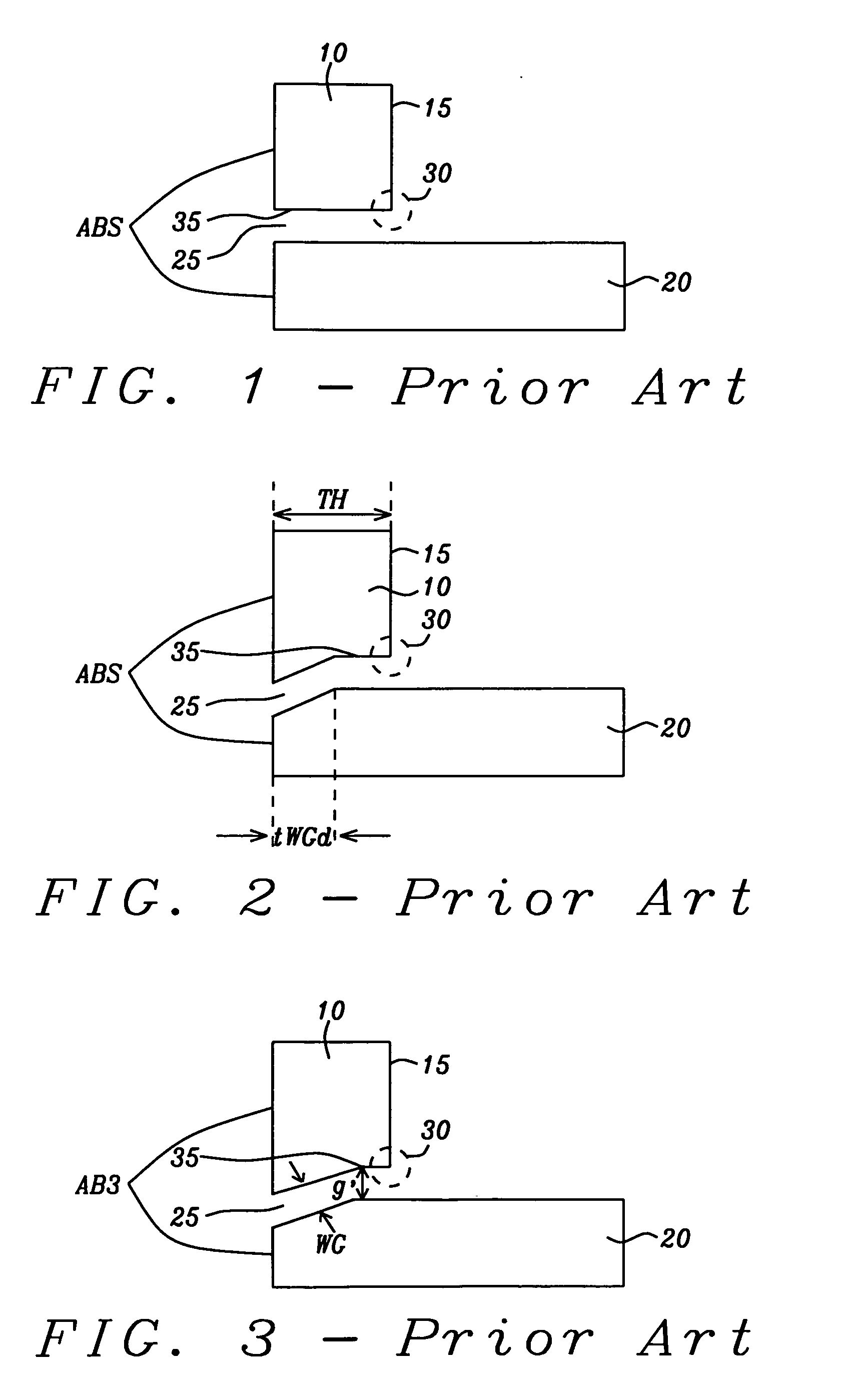
[0019]These objects will be met by a shield design that replaces the sharp right angle corner between the leading edge surface of the trailing shield (that forms the write gap) and the back surface of the shield, by either a progression of two gradual corners formed of obtuse angles or by a single rounded corner. In either case, the single sharp 90° corner at which flux shunting mainly occurs is eliminated. In additional embodiments, the elimination of sharp angles at which flux shunting occurs is also be applied to the design of a leading edge shield, thereby further improving the write head performance. Finally, embodiments of the invention will include a design of the write gap between the trailing shield and the main pole that significantly reduces the distance of minimum separation between the shield and the tapered edge of the pole that borders the write gap.

Problems solved by technology

Unfortunately, despite the benefits they provided, the presence of these shields inevitably reduce the field produced by the main pole because the basis of their operation is the removal of portions of the flux of that field.
This additional flux shunting has a disadvantageous effect on the writing ability of the pole.
These prior art examples do not disclose methods by which controlling the taper of a shield can advantageously maintain the writing characteristics of a main pole while minimizing the amount of flux that is shunted away from it.

Method used


Image

  • Writer shields with modified shapes for reduced flux shunting
  • Writer shields with modified shapes for reduced flux shunting
  • Writer shields with modified shapes for reduced flux shunting

Examples


first embodiment

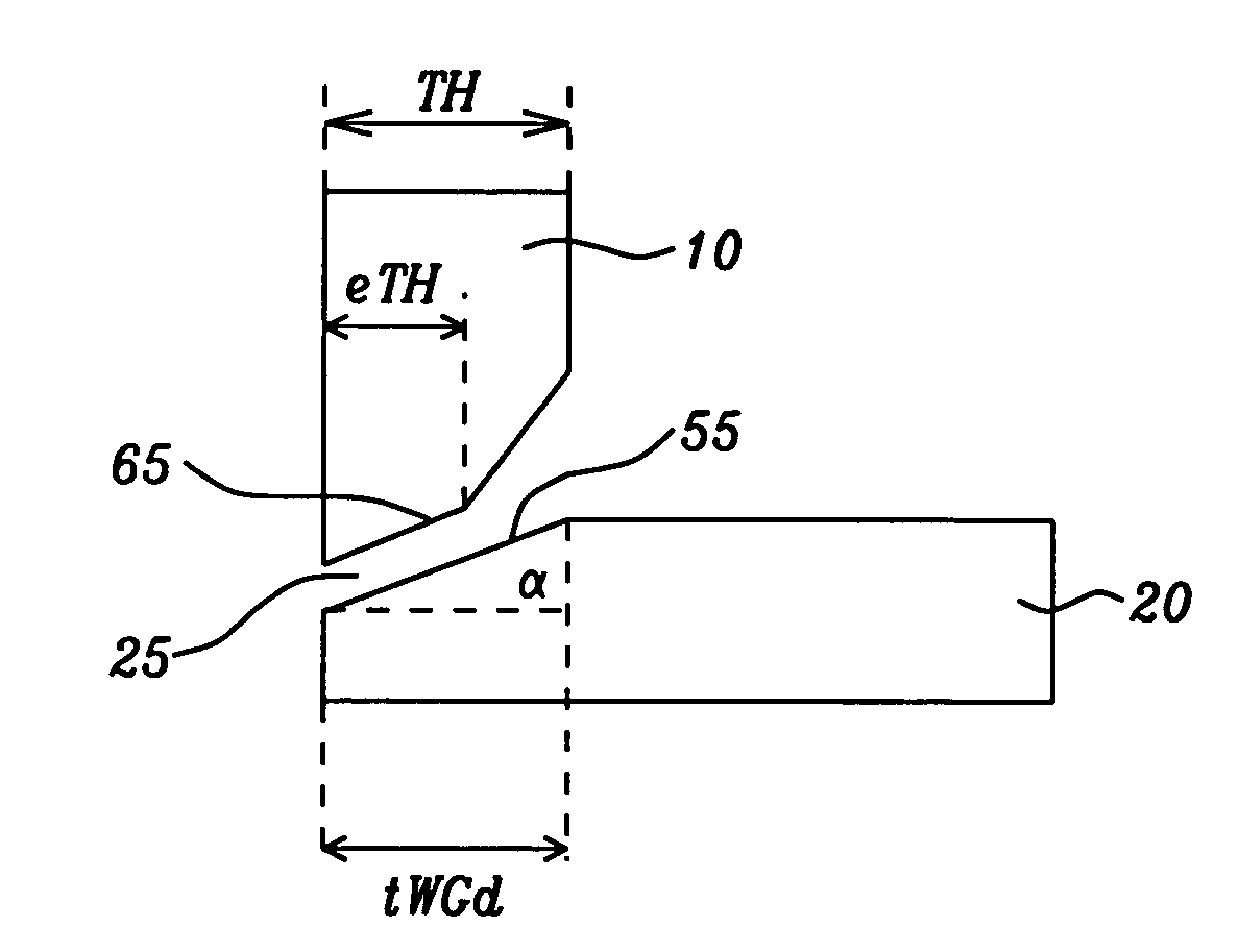
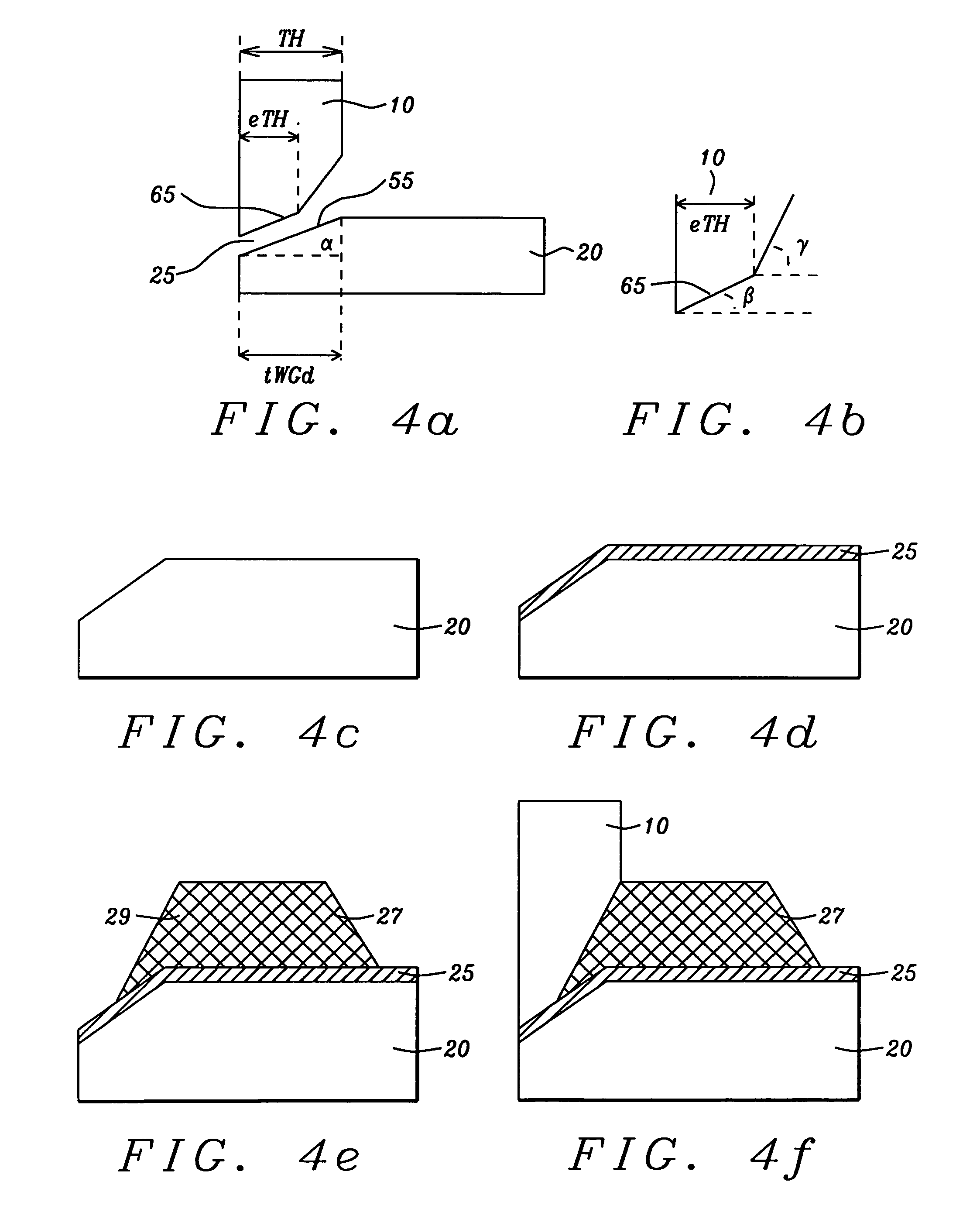
[0041]Referring first to FIG. 4a, there is shown schematically, in a cross-sectional view taken in a plane perpendicular to the ABS plane (5) of a main pole, a first preferred embodiment of the invention which is a PMR write head with a trailing shield (10) that is not of uniform thickness but has a maximum thickness, denoted TH (throat height). The main pole (20) has a maximum thickness, beyond a tapered portion (55), of between approximately 0.2 microns and 0.6 microns. The main pole is substantially of uniform thickness beyond this tapered portion. The tapered portion (55) is characterized by an angle with the horizontal (i.e., the horizontal being hereinafter defined as the direction perpendicular to the ABS plane), here denoted a. The upwardly tapered portion extends horizontally away from the ABS of the pole (5) for a horizontal distance denoted tWGd, which is between approximately 30 nm and 400 nm. The pole and shield are preferably formed of the magnetic materials FeNi, CoFe...

second embodiment

[0052]Referring first to FIG. 6a, there is shown schematically a second preferred embodiment of the invention in which a trailing shield (10) and a tapered main pole (20) are separated by a write gap (25) that is angled and not of uniform width. The backside edge (15) of the shield no longer forms a 90° angle with the leading edge of the shield (35) whose surface forms the write gap (25). Instead, a circled succession of two obtuse angles (32) creates a gradual corner without the sharp point of a 90° angle that became a source of flux leakage.

[0053]Referring to FIG. 6b, there is shown an enlarged view of the two obtuse angles (each being an angle α) encircled in (32) in FIG. 4a. The angles α and the height h which separates their vertices vertically (i.e. in a direction perpendicular to leading edge surface of the pole) are the parameters of the new shape. Their values range as follows: α in the range between approximately 120° and 170°, but preferably within the smaller range of be...

third embodiment

[0055]Referring to schematic FIG. 8, there is shown a configuration of a trailing shield (10) and a tapered main pole (20). In this embodiment, the (encircled) corner (33) formed between the backside surface (15) of the shield and the leading edge surface (35) bordering the rear of the write gap is formed as a rounded surface rather than a succession of obtuse angles as shown in FIG. 6a. The rounded corner, which would have a radius of curvature of between approximately 50 to 300 nm, achieves a similar result in that it eliminates sharp corners that are the source of flux leakage.


PUM


Abstract

A perpendicular magnetic recording (PMR) head is fabricated with a configuration of leading edge shields and trailing edge shields that reduce the leakage of flux between the main pole and the shields. The reduction of leakage is achieved by eliminating the sharp 90° corner between the backside surfaces of the shields and the surfaces adjacent to the main pole. In one embodiment the corner is replaced by two successive acute angles, in another embodiment it is replaced by a rounded surface. In a final embodiment, leakage between the pole and trailing edge shield is achieved by shortening the length of the write gap by forming the shield with a double taper.

Description

BACKGROUND OF THE INVENTION[0001]1. Field of the Invention[0002]This invention relates to the fabrication of a perpendicular magnetic recording (PMR) write head whose main pole is at least partially surrounded by shields formed of magnetic material. In particular it relates to such a head that is shielded at its trailing edge by a shield that is tapered in a plane perpendicular to the ABS (air bearing surface) plane.[0003]2. Description of the Related Art[0004]The increasing need for high recording area densities (up to 1 Tb / in2) is making the perpendicular magnetic recording head (PMR head) a replacement of choice for the longitudinal magnetic recording head (LMR head).[0005]By means of fringing magnetic fields that extend between two emerging pole pieces, longitudinal recording heads form small magnetic domains within the surface plane of the magnetic medium (hard disk). As recorded area densities increase, these domains must correspondingly decrease in size, eventually permitting...

Claims


Application Information

Patent Timeline
IPC IPC(8): G11B5/17
CPCG11B5/1278G11B5/3116G11B5/3163G11B5/3146G11B5/312
Inventor BAI, ZHIGANGDOVEK, MORISWU, YAN
Owner HEADWAY TECH INC
Learn More