Method for forming a mortise and tenon for tool free joinder, and joint assembled therefrom

a technology which is applied in the field of mortise and tenon joints, can solve problems such as the risk of different physical characteristics, and achieve the effect of preventing damage to components

Inactive Publication Date: 2012-02-23
SCHOOLEY FRANK W
View PDF3 Cites 4 Cited by
  • Summary
  • Abstract
  • Description
  • Claims
  • Application Information

AI Technical Summary

Benefits of technology

[0022]Observably, the tenon is peripherally semicircular in cross section. In order to permit a flush, sturdy connection between the mortise and tenon, the router is programmed to cut undercuts at a location formed by the semicircular extension of the tenon. The undercuts are formed as cutaways of a portion of the tenon shoulder such that the mortise will seat against the horizontal plane of the tenon, and eliminate any stress riser which can result in a crack or help break any sharply angled corner under load. The combined height of the undercut and the tenon shoulder immediately thereabove is equal to the thickness of the first material so as to avoid any gaps between the first material and the tenon.
[0023]It should be appreciated that, by design, each kit of parts created in accordance with the invention further includes a tool which is also created from the same substrate and in the same manner by the router in accordance with a programmed pattern. This also becomes the only tool necessary to complete any assembly and is generally intended to be included with each kit of parts. It is understood that forming the hammer from the same material that is used to form the first material and the second material assures that the hammer and the mortise and tenon joint will have the same relative size, thickness, hardness and specific density such that the hammer will not mark or dent the components of the mortise and tenon joint during assembly. The hammer head includes two striking surfaces at either end. In another preferred embodiment of the instant invention, at least one of the two striking surfaces is rounded to prevent damage to the components of the mortise and tenon joint during the assembly thereof. Further, the hammer may include rounded shoulders or corners, also to prevent damage to the components of the mortise and tenon joint during the assembly thereof.

Problems solved by technology

Another problem associated with construction projects that require the joinder of differing materials—in comparison to a single material—is that inherent in the differing materials selected is, per force the risk of different physical characteristics, which require the use of different tools, cutting rates and cutting materials to conform mortise, on one item of one type of material, to tenon, on another item of another type of material.

Method used


Image

  • Method for forming a mortise and tenon for tool free joinder, and joint assembled therefrom
  • Method for forming a mortise and tenon for tool free joinder, and joint assembled therefrom
  • Method for forming a mortise and tenon for tool free joinder, and joint assembled therefrom

Examples


Embodiment Construction

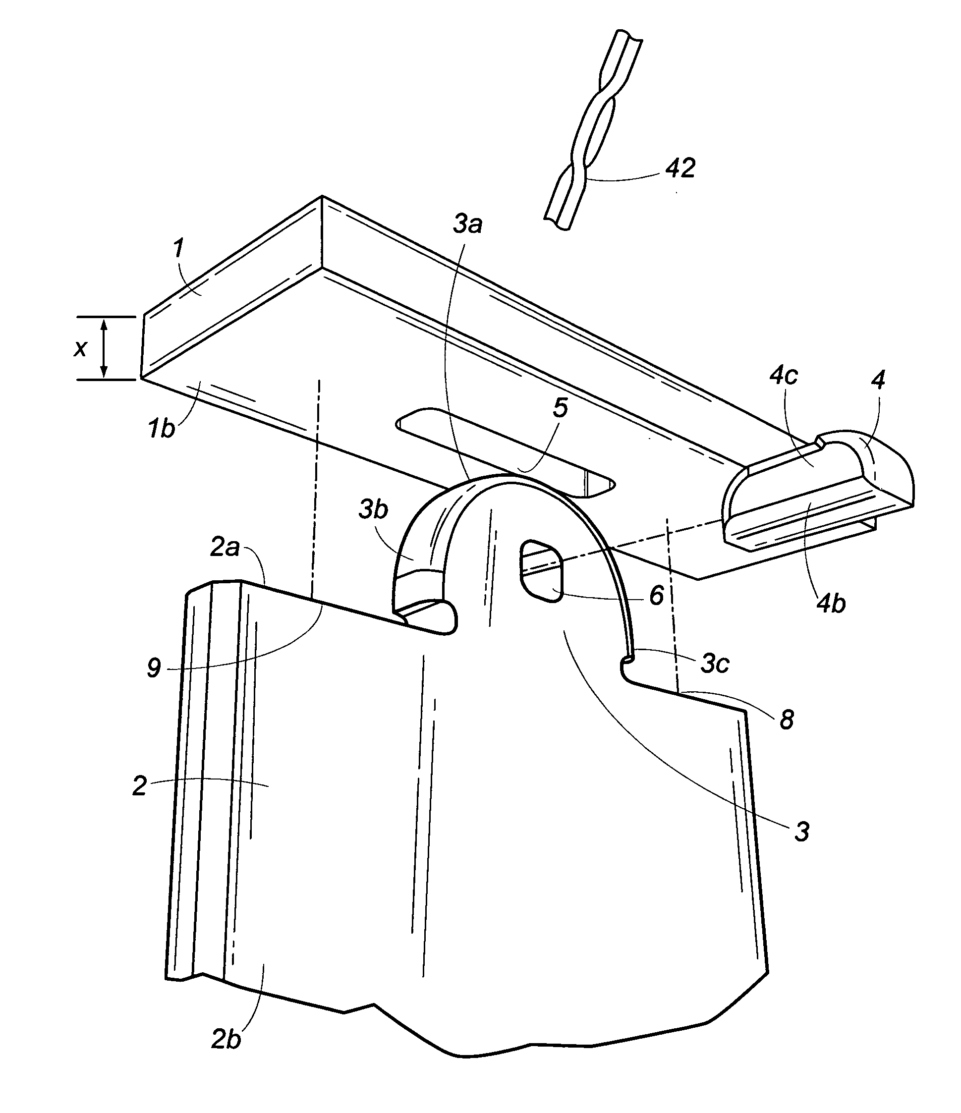
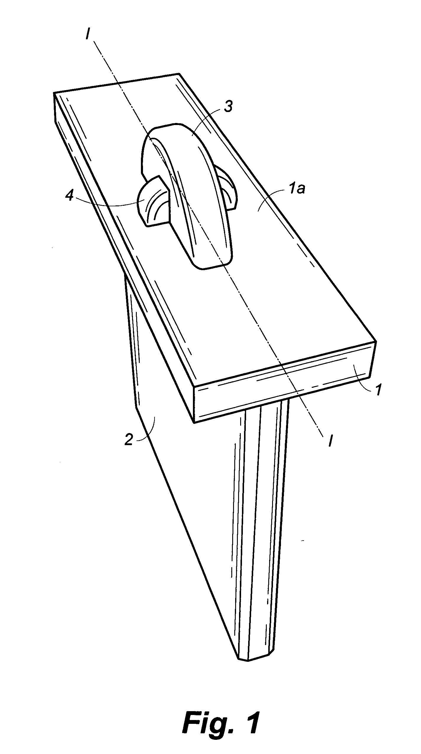
[0034]In accordance with the subject invention, FIG. 1 shows one embodiment of the present invention in which the mortise and tenon joint of the instant invention are shown in assembled form, such that two members are joined together. In particular, first member 1 includes a top 1a and bottom 1b (shown in FIG. 2). Second member 2 includes tenon 3 at the top of second member 2, such that tenon 3 extends upwardly through the bottom of first member 1 through an aperture (or mortise) in first member 1. Locking peg 4 is then inserted horizontally through an aperture (or mortise) in the top portion of tenon 3.

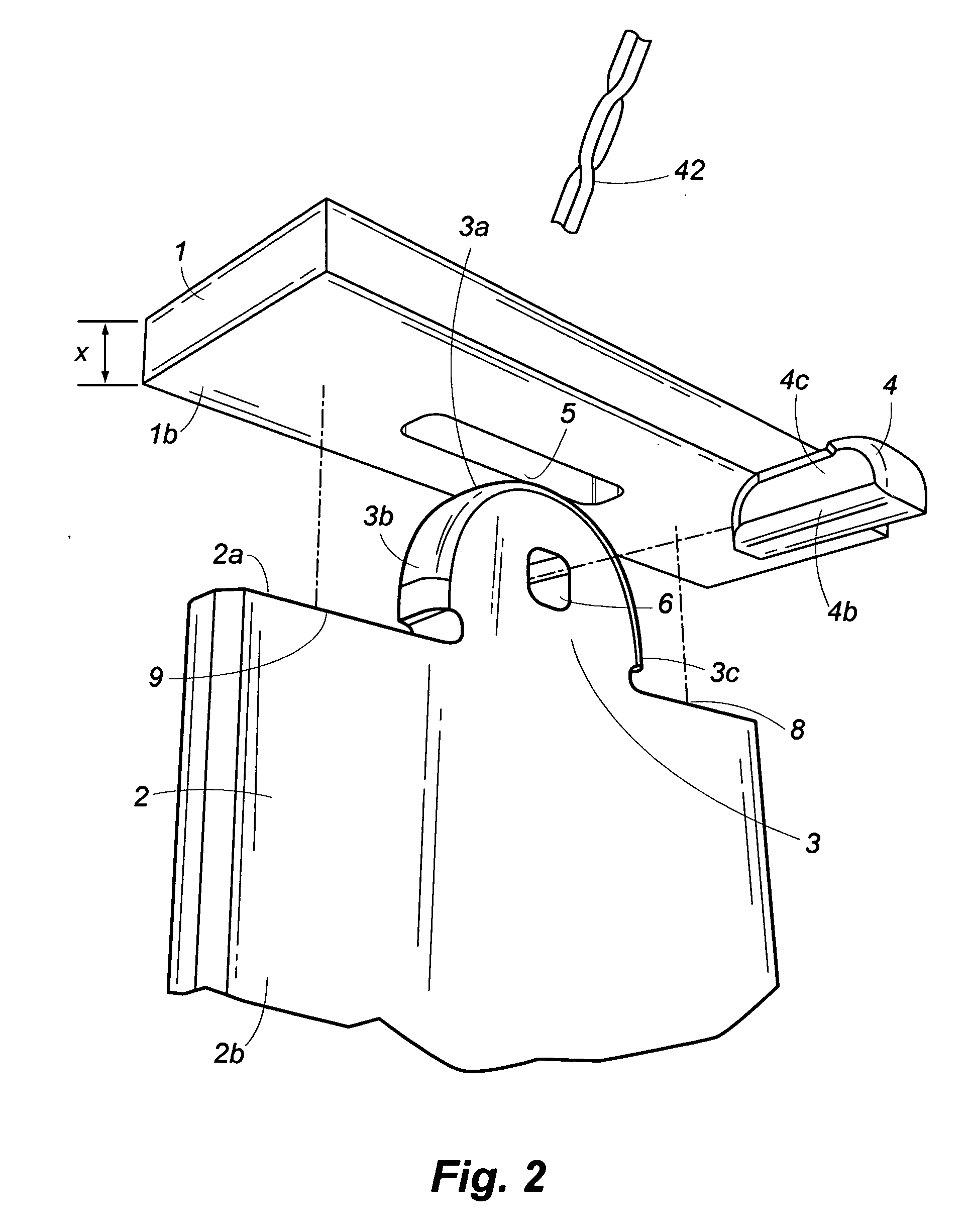
[0035]As shown in FIGS. 2-3, mortise 5 is shown as the preferred rectilinear configuration through member 1, such that mortise 5 extends through top 1a (as shown in FIG. 1) and bottom 1b of first member 1 forming an aperture that comprises the mortise. It should be appreciated that all cuts shown, save the rounding of the surfaces of tenon 3, are created by the same bit 42.

[0036]Seco...


PUM


Abstract

A method for making two items and their joinder, one having a mortise and the other a tenon to enable a substantially flush, contiguous, void-free abutment. All cuts are made with a straight router bit having a diameter “Y” from a single sheet of substrate stock having a thickness “X” such that Y≦(½)X. In the mortise, corners are given a rounding defined by Y and a length “L1”. The tenon has a width substantially equal to L1 and a height “Z”, such that Z>2X. On the item having the tenon, at each of the two opposing locations defined by the intersection of the tenon with the shoulder of the item from which the tenon is cut (and also defining a shoulder line from shoulder to shoulder), an additional undercut is given at a minimal, linear displacement sufficient to enable, upon joinder, the mated surfaces of the two items to appear in flush, contiguous, void-free abutment with minimal reduction in the strength of the join. The tenon further has a substantially rectangular peg-receiving aperture set at distance substantially equal to X from the shoulder line, and having a height “H”, such that H=X. A locking peg has a cross-section substantially conforming with the peg-receiving aperture. Rounding of the peg proximate to the undercuts is made with a rounder at a radial rounding substantially equal to (½)Y. The product of the method is also shown.

Description

FIELD OF THE INVENTION [0001]The instant invention relates to the field of joinery of the surfaces of two items in secure, flush abutment for woodworking, masonry and metal-working building applications, and more specifically to mortise and tenon joints and methods for forming just joints and the assemblies resulting therefrom, formed in a manner that minimizes scrap without the use of multiple cutting tools, provides a basis for kitting a building application as a kit of parts, and enables simple on-site assembly into final functional construction without requiring an array of on-site tooling.BACKGROUND OF THE INVENTION [0002]Joining the surfaces of two items in secure flush abutment has specific application and need in woodworking, masonry, metal working, and other fields. In searching for a method of forming joints from the materials to be joined themselves, and in determining a reliable, repeatable joint design that will permit easy and rapid assembly under a multiplicity of cir...

Claims


Application Information

Patent Timeline
Patent Type & Authority Applications(United States)
IPC IPC(8): F16B12/10B27F1/00
CPCY10T403/7094F16B12/125F16B2200/30
Inventor SCHOOLEY, FRANK W.
Owner SCHOOLEY FRANK W
Why Eureka
Try Eureka