
System and method for monitoring and controlling physical structures

Inactive Publication Date: 2012-02-23
GENERAL ELECTRIC CO
View PDF4 Cites 33 Cited by
  • Summary
  • Abstract
  • Description
  • Claims
  • Application Information

AI Technical Summary

Benefits of technology

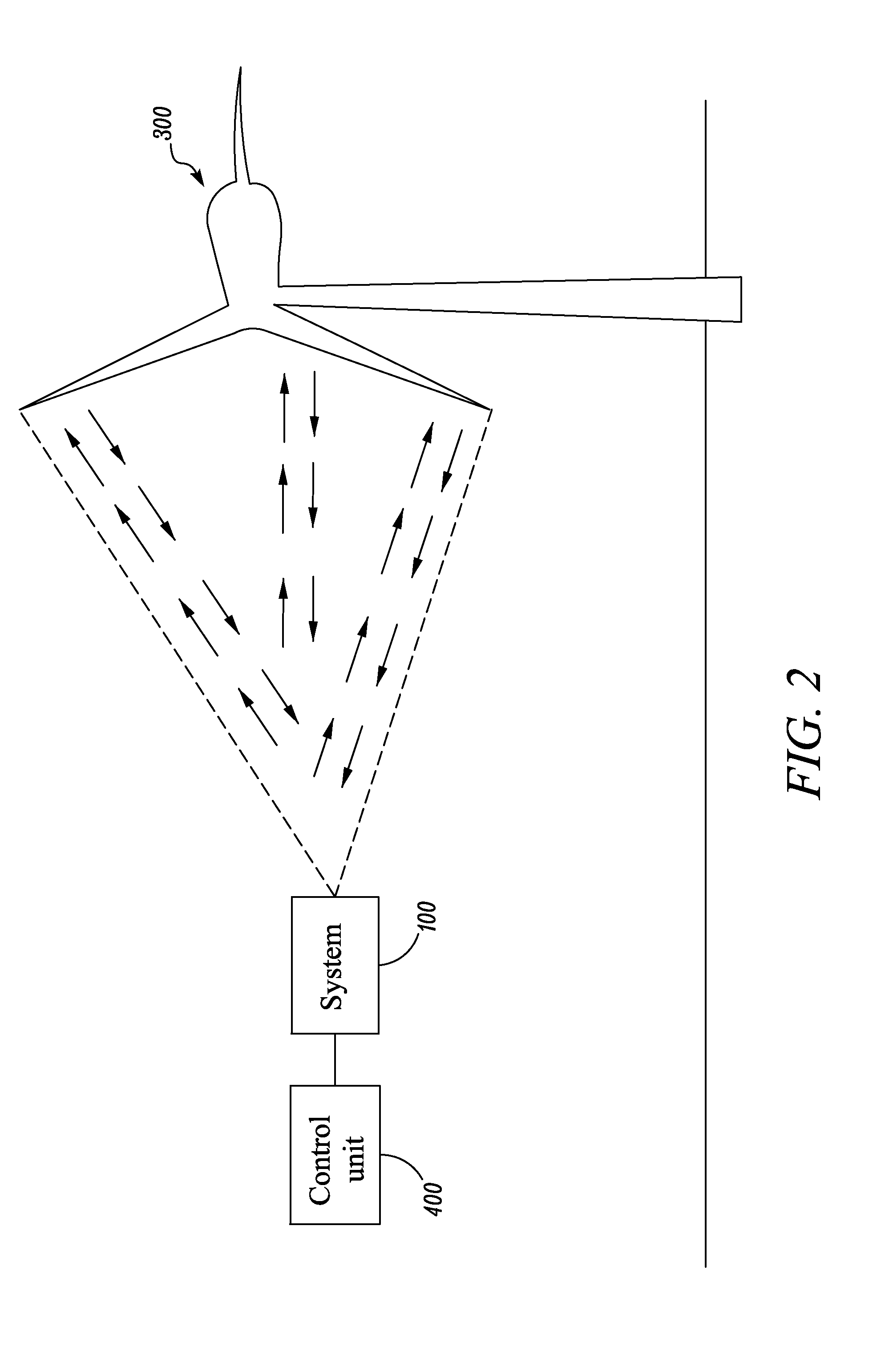
[0007]A system for controlling a wind turbine includes a light source adapted to generate light pulses. The system also includes a beam scanner coupled with the light source. The beam scanner is adapted to scan the light pulses over a predefined capture area of the wind turbine. The system further includes a photo-detector adapted to receive backscattered light pulses from the wind turbine and subsequently provide a signal corresponding to each of the light pulse. The system further includes a pre-processing module to adjust a threshold of the signal based on a normalized value of a detected peak value of the signal. The system also includes an association module to associate a time of flight with each of the received backscattered light p

Problems solved by technology

Typically, the wind turbines are exposed to variable aerodynamic load due to varying wind conditions.
Moreover, the wind turbines are also exposed to unpredictable harsh weather conditions.
These sensing feedbacks may be used for monitoring the physical health of the wind turbine components, which upon going unnoticed may lead to catastrophic failure of the wind turbine.
However, such sensors are subjected to harsh weather conditions, such as high wind speeds, rainfall, snow, hail and the like, which may shorten the life of the sensors.
Further, the outboard sensor system also has low spatial resolution limited by the number of the sensors that may be installed on the blades of the wind turbine.
Moreover, a system of triaxial accelerometers embedded in each blade of the turbine may be used for measuring the operating frequencies of the turbine blades and may alert when a significant deviation from normal operating parameters is monitored, either from excessive stress, or blade damage.
However, this approach also has a low spatial resolution and a limitation on the low-frequency response.

Method used


Image

  • System and method for monitoring and controlling physical structures
  • System and method for monitoring and controlling physical structures
  • System and method for monitoring and controlling physical structures

Examples


Embodiment Construction

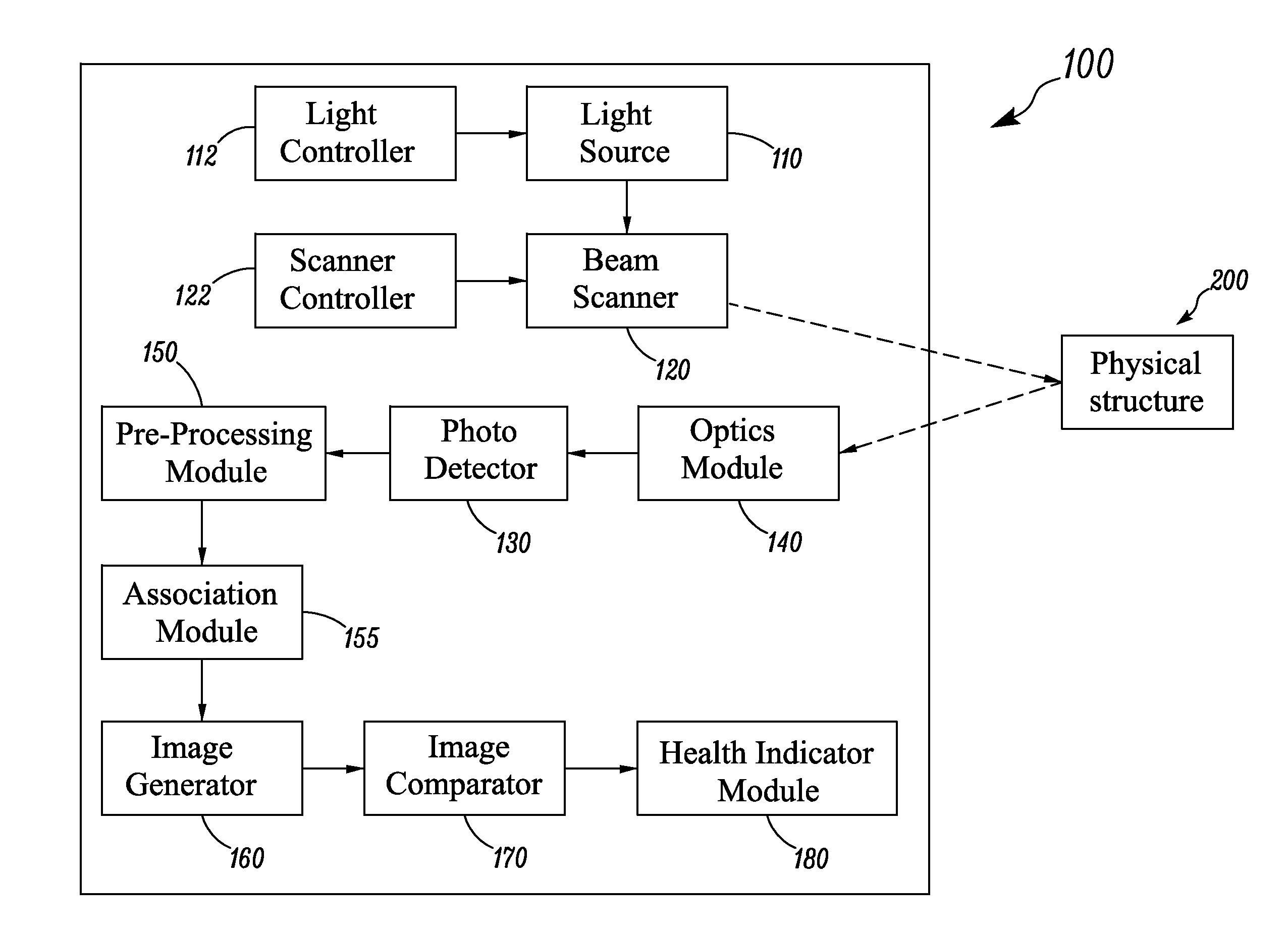
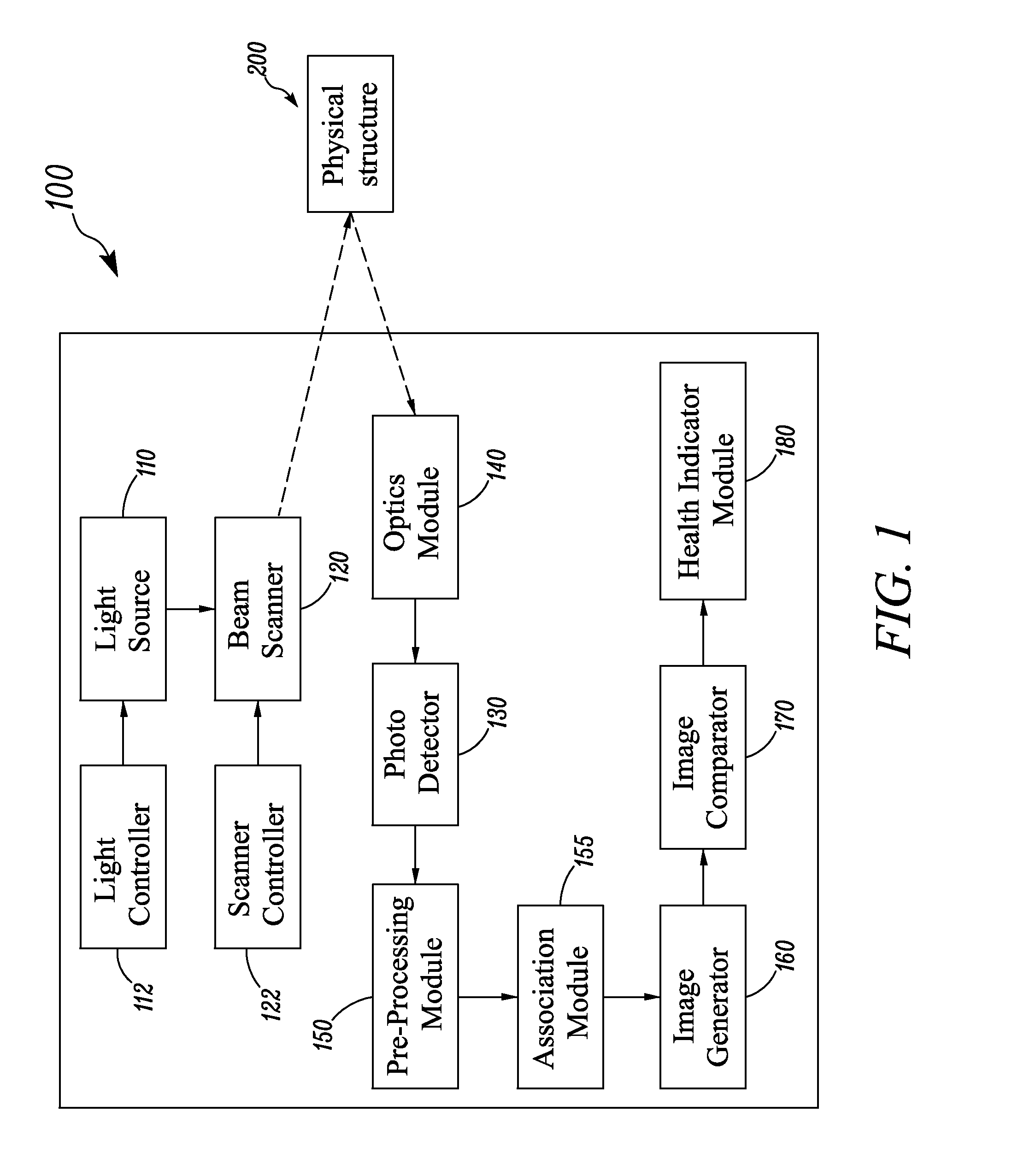
[0013]FIG. 1 illustrates a system 100 for monitoring the health of a physical structure 200, according to one embodiment. For example, the system 100 may be used in conjunction with the physical structure 200, which may be a wind turbine, a tower, a terrestrial structure, and an aerial structure, for monitoring the health thereof.

[0014]The system 100 may include a light source 110. The light source 110 may be adapted to generate a light beam, constituted by short light pulses. In an exemplary embodiment, the light source 110 may be a laser source, which is adapted to generate a laser beam. The terms “light beam” and “light pulses” may be hereinafter alternatively referred to as “light beam” and “light pulses.”

[0015]The light source 110 may be a gas laser, a chemical laser, a dye laser, a metal-vapor laser, a solid-state laser, a semiconductor laser and the like. Further, in an exemplary embodiment, the light source 110 may be adapted to generate short light pulses of less than or eq...


PUM


Abstract

A system for controlling a wind turbine is disclosed. A system includes a light source and a beam scanner to scan the light pulses over the wind turbine. The system further receives backscattered light pulses and subsequently, provides a signal corresponding to the light pulses. The system adjusts a threshold of the signal based on a normalized value of a detected peak value of the signal. The system associates a time of flight with each of the received backscattered light pulse. The system generates an image of the wind turbine based on the time of flight associated with the light pulses and subsequently, compares the generated image with at least one known image of the wind turbine. The system generates a health profile of the wind turbine based on the comparison and subsequently, change one or more parameters of the wind turbine based on the health profile.

Description

BACKGROUND[0001]Embodiments presented herein relate generally to monitoring and controlling systems, and more specifically to a system for monitoring and controlling a physical structure.[0002]Physical structures such as wind turbines are known as an important source for renewable energy. Wind turbines convert wind energy into electrical energy. Specifically, wind blowing over the blades causes the blades to produce ‘lift’ and thus rotate about a shaft. Further, the shaft drives a generator which produces electrical energy. Typically, the wind turbines are exposed to variable aerodynamic load due to varying wind conditions. Moreover, the wind turbines are also exposed to unpredictable harsh weather conditions. In such instances, it is desirable to know the wind turbine components' spatial behavior, such as overall bending and twisting along the blades length, tower top displacement and vibration, yaw angle, and the like. These sensing feedbacks may be used for monitoring the physica...

Claims


Application Information

Patent Timeline
IPC IPC(8): F03D7/04G06K9/00G01S17/89
CPCF03D7/042F05B2260/80F05B2270/80F05B2270/804Y02E10/723G01S17/89G06T7/001G06T2207/10028G06T2207/30164G01S17/88Y02E10/72
Inventor WU, JUNTAOZHENG, DANIANLIU, PINGLEE, BOON KWEEMONK, DAVID JAMESCHEN, QINGRAHAM, III, FREDERICK GORUMSPRATT, WILLIAM THOMAS
Owner GENERAL ELECTRIC CO
Learn More