Dual Fuel Gas Heater

a gas heater and dual fuel technology, applied in the field of gas heaters, can solve the problem that the manufacturer cannot supply a conversion kit, and achieve the effect of enhancing the natural convective curren

Active Publication Date: 2012-02-23
COPRECITEC
View PDF5 Cites 3 Cited by
  • Summary
  • Abstract
  • Description
  • Claims
  • Application Information

AI Technical Summary

Benefits of technology

[0006]A dual fuel gas burner is provided for use in a vent free heater. Embodiments of the dual fuel vent free gas burner can be used in free standing heaters, wall mount heaters, gas fireplaces, or other vent free heaters as is known in the art. A dual fuel vent free gas heater provides convective and / or radiant heat preferably to an indoor environment. The heater may be designed to use natural convective air currents and may optionally have a fan enhancing the natural convective currents within the heater. Alternatively, a fan may be used to force the gases and / or air within the heater at desired flow patterns which may be counter to natural convective forces.

Problems solved by technology

It is not permitted for a manufacturer to supply a conversion kit for an unvented gas heater to convert from one fuel source to another.

Method used


Image

  • Dual Fuel Gas Heater
  • Dual Fuel Gas Heater
  • Dual Fuel Gas Heater

Examples


Embodiment Construction

[0025]The following description describes embodiments of a dual fuel vent free heater. In the following description, numerous specific details and options are set forth in order to provide a more thorough understanding of the present invention. It will be appreciated, however, by one skilled in the art that the invention may be practiced without such specific details or optional components and that such descriptions are merely for convenience and that such are selected solely for the purpose of illustrating the invention. As such, reference to the figures showing embodiments of the present invention is made to describe the invention and not to limit the scope of the disclosure and claims herein.

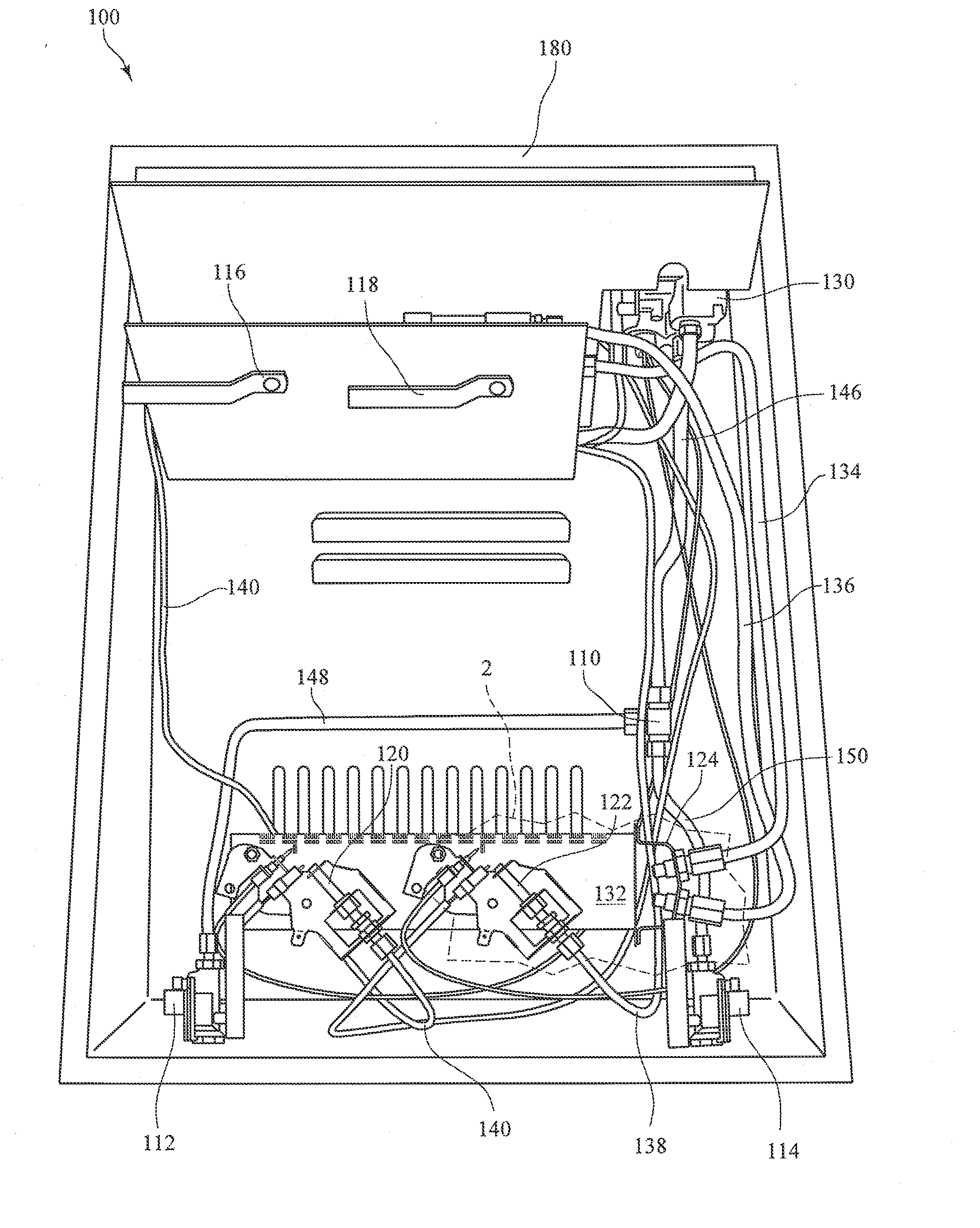
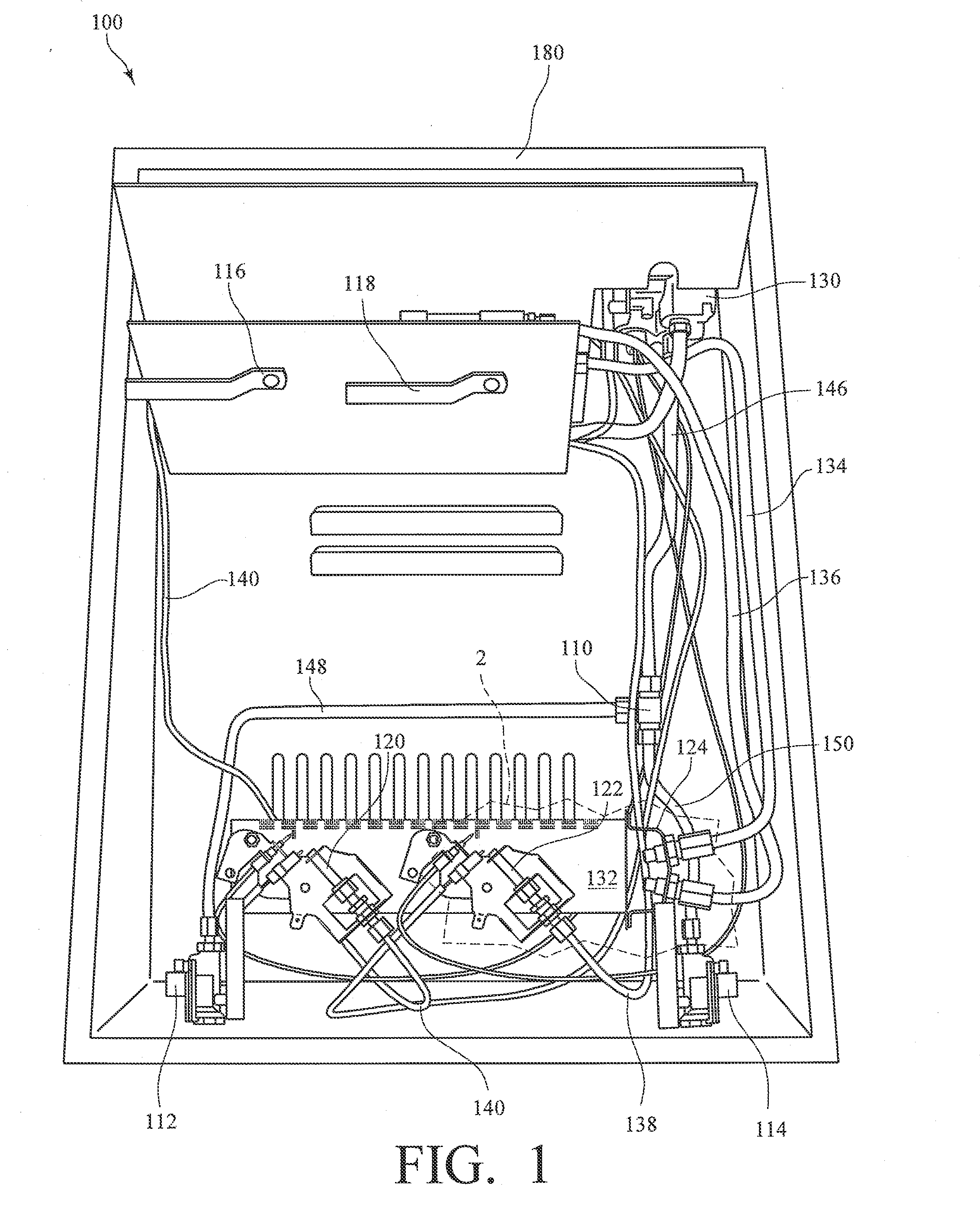
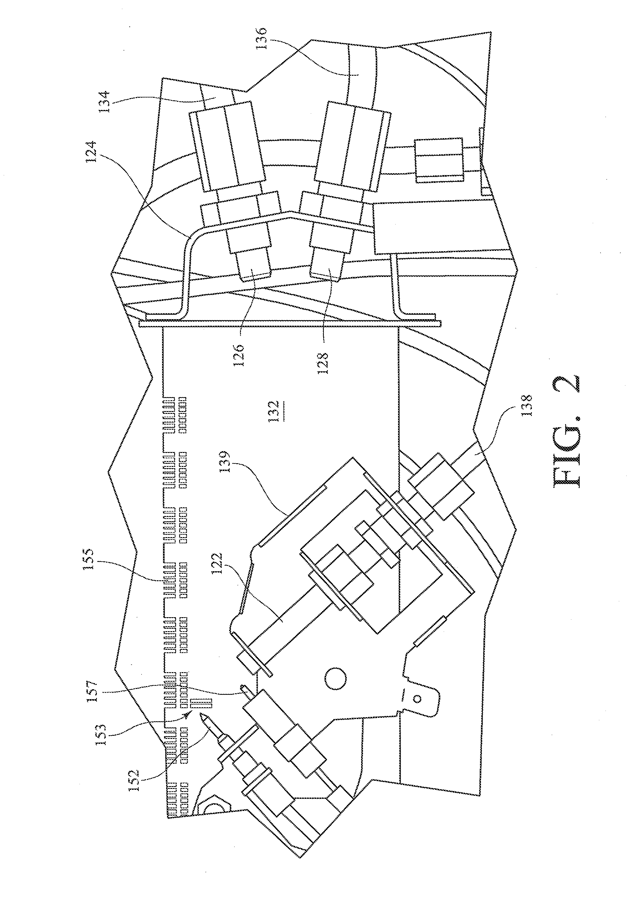
[0026]FIGS. 1, 2 and 3 show a dual fuel vent free heater 100. FIG. 1 shows the component parts of dual fuel vent free heater 100 in a housing 180 and FIG. 3 shows the flow diagram of heater 100. Dual fuel vent free gas heater 100 comprises a gas burner 132 having a plurality of gas outlet por...


PUM


Abstract

A dual fuel vent free gas heater. In one implementation the heater includes a gas burner adapted to receive one of a first type of gas or of a second type of gas with a first pilot burner intended to receive the first type of gas and a second pilot burner intended to receive the second type of gas. A first temperature sensor is located adjacent the first pilot burner and a second temperature sensor is located adjacent the second pilot burner. A normally closed thermal switch is coupled to the first temperature sensor and located in the electrical flow path between a voltage source and a gas control valve actuator, the thermal switch configured to open when the temperature detected by the first temperature sensor exceeds a predetermined temperature indicative that the second type of gas is being delivered to the first pilot burner.

Description

CROSS-REFERENCE TO RELATED APPLICATIONS[0001]This application is related to U.S. Pat. No. 7,766,006 and U.S. application Ser. Nos. 12 / 643,880, 12 / 237,131 and 12 / 237,136.FIELD OF THE INVENTION[0002]The present invention relates generally to gas heaters and, more particularly, to unvented gas heaters.BACKGROUND[0003]Unvented gas heaters are designed to be used indoors without pipes, ducts, or other conduit to vent the heater's exhaust to the exterior atmosphere. Vent free gas heaters typically include one or more gas burners and optionally one or more ceramic containing heating elements in a housing. The gas and air mix in the heater where combustion takes place. These heaters may have a blower to force air flow through the heater providing the release of heated gases or convective heat.[0004]Unvented gas heaters have been designed to be free standing, mounted on a wall, or in a decorative housing such as a vent free fireplace. The housing providing a vent free fireplace is typically ...

Claims


Application Information

Patent Timeline
Patent Type & Authority Applications(United States)
IPC IPC(8): F23N1/00
CPCF23D23/00F23D2208/00F23D2900/00014F23D2900/21004F23N1/005F23N5/022F23N2021/10F23N2025/16F23N2037/08F23N1/002F23N2221/10F23N2225/16F23N2237/08
Inventor MATEOS MARTIN, RUBENANTXIA URIBETXEBARRIA, JOSE JOAQUIN
Owner COPRECITEC
Why Eureka
Try Eureka