Device for generating a cooling air flow in a preferential flow direction for cooling electrical components

a technology of electrical components and flow direction, which is applied in the direction of semiconductor devices for light sources, semiconductor/solid-state device details, lighting and heating apparatus, etc., can solve the problems of inability to prevent the risk of overheating of led illuminants, inadmissible overheating of illuminants or lamps, etc., to achieve reliable cooling effect, enhance natural convection, and easy to implement

Inactive Publication Date: 2012-03-01
GOODRICH LIGHTING SYST
View PDF6 Cites 6 Cited by
  • Summary
  • Abstract
  • Description
  • Claims
  • Application Information

AI Technical Summary

Benefits of technology

[0016]By the oscillation movement, there is first generated an air movement between the channel walls. In the region opposite the oscillating partial region, this air movement will be deflected, namely generally to all sides. By the effect of the anisotropic surface structure, the thus deflected air flow will now be largely deflected into the preferential flow direction, or, expressed in a different manner, the air will flow primarily in the preferential flow direction. On the whole, a net air flow is generated in the preferential flow direction.
[0017]Thus, according to the arrangement proposed by the invention, the air movement oscillating orthogonally to the extension of the channel walls is deflected into an air movement between the two channel walls, said air movement between the two channel walls streaming at different rates in the most different directions parallel to the channel walls and between the latter while, however, due to the anisotropic surface structure, a net or preferential flow direction is obtained. When applying this concept to the cooling plate elements of a cooling body, the device according to the invention can enhance the natural convection in that the cooling plate elements are vertically oriented and the anisotropic surface structure is oriented in such a manner that the preferential flow direction is pointing upward.
[0018]An essential advantage of the device of the invention resides in its reliable cooling effect, while the need for moving component parts, such as e.g. inlet and/or outlet valves operating in opposite senses to each other, is obviated (except for said oscillating partial region of at least one of the channel walls and respectively of an element arranged therebetween). Particularly, no active cooling devices such as e.g. ventilators are required. In aircraft industry, such active cooling measures are presently not admissible because it is feared that the cooling would be considerably impaired in case of a fallout of the active cooling devices such as e.g. ventilators and the like. Apart from the above advantage, the device of the invention and the cooling method of the invention will guarantee their functionality even under extreme ambient conditions. The influence of such ambient conditions or extreme external influences is to be expected on the landing gear of aircraft where the device would be exposed to aggressive media, dirt, flying stones or grave...

Problems solved by technology

Further, there exist illumination applications wherein the light is switched on only for a short time, while, however, due to the power density and the available (cooling) surface, there is a ri...

Method used


Image

  • Device for generating a cooling air flow in a preferential flow direction for cooling electrical components
  • Device for generating a cooling air flow in a preferential flow direction for cooling electrical components
  • Device for generating a cooling air flow in a preferential flow direction for cooling electrical components

Examples


Embodiment Construction

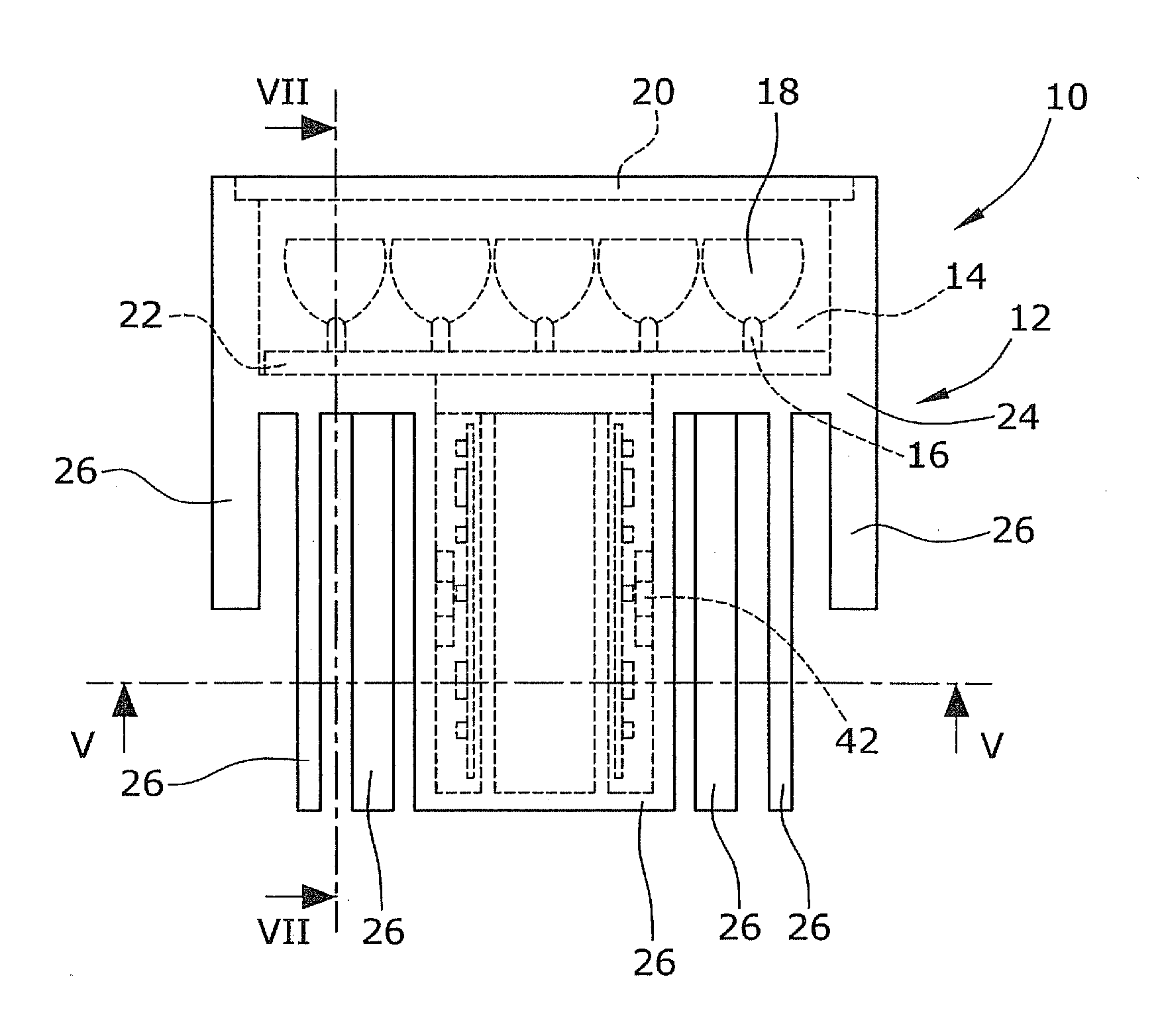
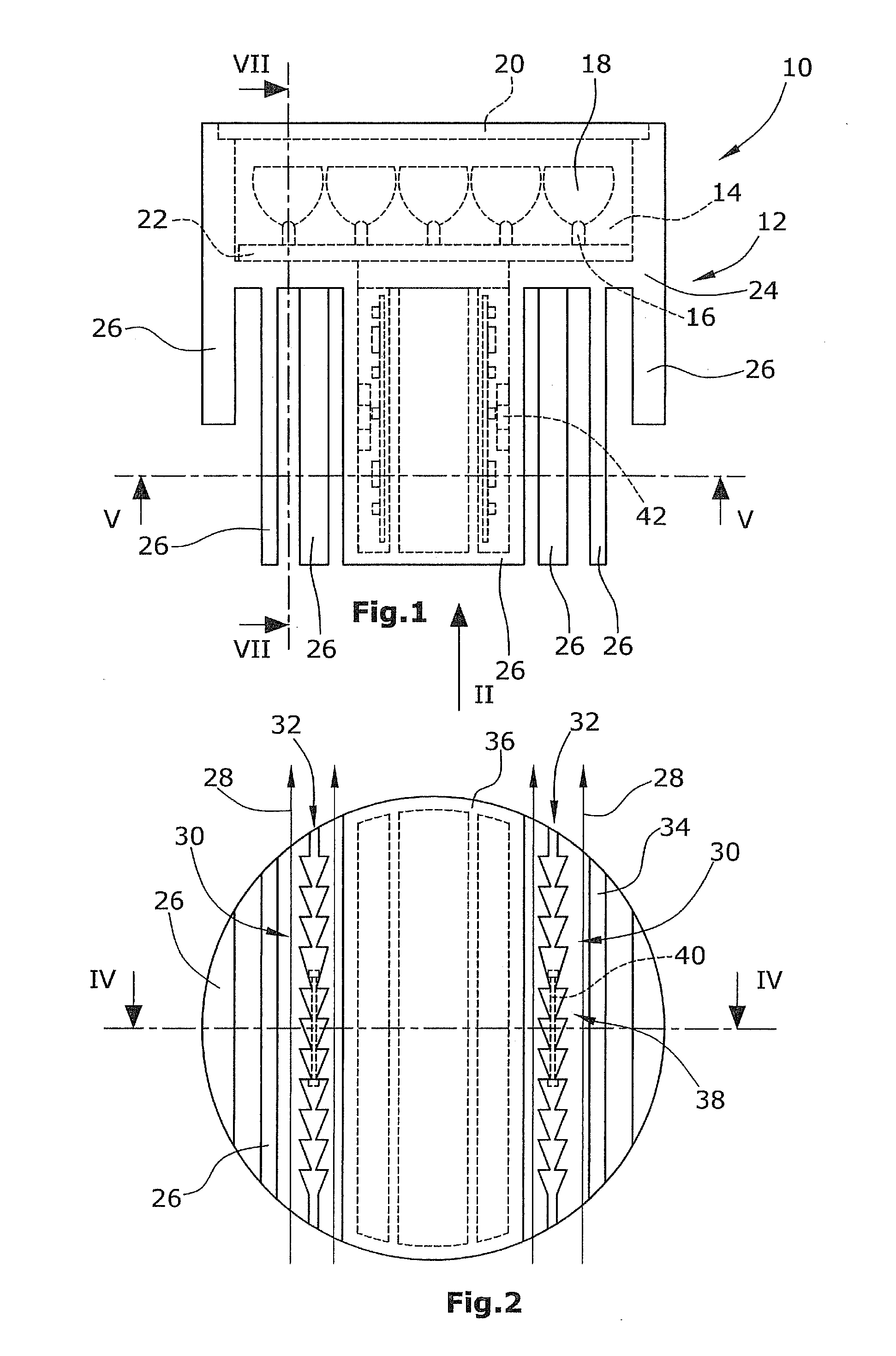
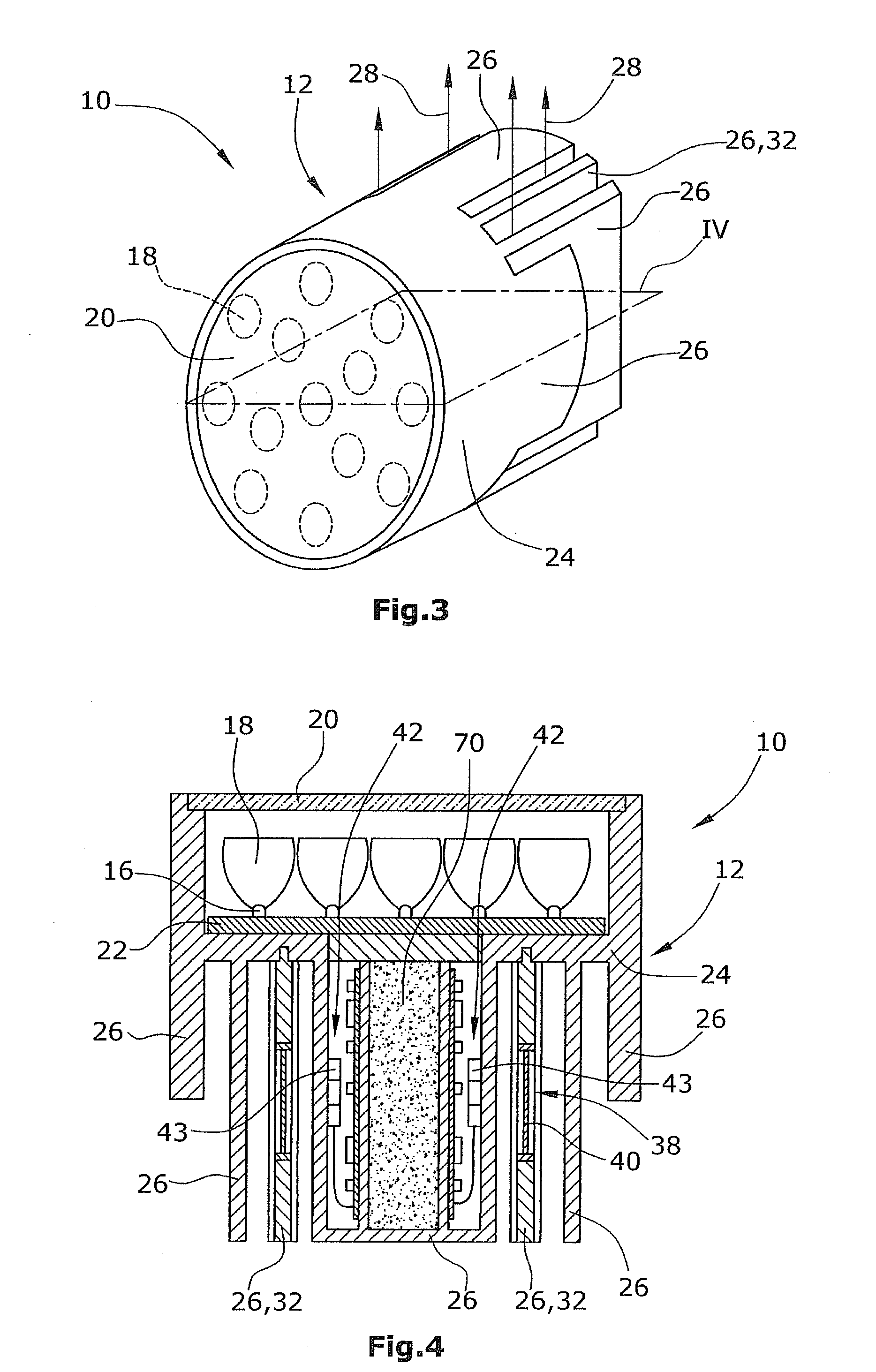
[0042]In FIGS. 1 to 3, an LED aircraft light 10 is shown in lateral, rear and perspective view. Said aircraft light 10 comprises a housing 12 provided with a receiving chamber 14. In said receiving chamber 14, a plurality of LEDs 16 are arranged whose light will be fed into (TIR) light conductors 18 which in turn will radiate this light to the outside via a lighting plate or a transparent cover 20. It should be noted that the use of TIR is not absolutely necessary for the invention. Within the framework of the invention, also other LED illuminants with or without light-conducting optical elements can be used.

[0043]In the present embodiment, said LEDs 16 are high-performance LEDs and are held on a common support plate 22. Said support plate 22 is in thermally conductive contact with a cooling body 24 which can form said housing 12—or a part thereof—of aircraft light 10 and which comprises individual cooling plate elements 26. Said cooling body 24 is provided with a device for generat...


PUM


Abstract

The device for generating a cooling air flow in a preferential flow direction for cooling electrical components, particularly LEDs, comprises a first and a second channel wall (34,36) having mutually confronting inner sides, and an oscillation drive means (42) for generating an oscillating movement of at least a partial region (38) of at least one of said channel walls (34,36) in the direction toward the other channel wall and away therefrom. The inner side of at least one of said two channel walls (34,36) has a surface structure (30) designed for anisotropic flow, which has a smaller flow resistance coefficient in the preferential flow direction (28) than in a direction extending at an angle to the preferential flow direction (28) and particularly in a direction extending opposite to the preferential flow direction (28).

Description

RELATED CROSS-REFERENCING[0001]The present invention claims the priority of European Patent Application No. 10 174 853.1 filed on Sep. 1, 2010, the disclosure of which is incorporated herein by reference.BACKGROUND OF THE INVENTION[0002]1. Field of the Invention[0003]The present invention relates to a device for generating a cooling air flow in a preferential flow direction for cooling electrical components, particularly electro-optical components such as e.g. LEDs. The present invention particularly relates to the integration of a device of the above type into a cooling body for cooling electrical components, particularly electro-optical components such as e.g. LEDs.[0004]2. Description of the Prior Art[0005]On the sector of land and air vehicles, efforts have been under way for many years to install LEDs as a replacement of conventional illuminants of the type with filaments or of the gas discharge type. This trend is favored by the recent introduction of high-performance LEDs on ...

Claims


Application Information

Patent Timeline
IPC IPC(8): F24H3/02
CPCF21V29/02F21Y2101/02H01L23/473F21V29/63H01L2924/0002H01L2924/00F21Y2115/10F21V29/83
Inventor HESSLING, ANDRE
Owner GOODRICH LIGHTING SYST
Why Eureka
Try Eureka