Bistable switching method and latching relay using the same

a latching relay and switching method technology, applied in electromagnetic relays, electrical apparatus, electrical relay details, etc., can solve the problems of complex and huge construction, difficult to adapt mono stable relays, and difficult to use manual switches in electrical systems, so as to improve the power consumption and stable state.

Active Publication Date: 2012-03-01
LIANG CHIH CHUAN
View PDF18 Cites 11 Cited by
  • Summary
  • Abstract
  • Description
  • Claims
  • Application Information

AI Technical Summary

Benefits of technology

[0026]As described above, the bistable switching method of the invention and the bistable latching relay of the invention utilize currents to rotate the rotor shaft, which is covered by the cylindrical permanent magnet. The bistable latching relay is able to stay in one of the stable states (closed state and open state) after the currents on the coil of the bistable latching relay are turned off. Besides, the bistable latching relay of the invention includes fewer components and the conversion efficiency of the bistable latching relay, which is constructed of two permeability materials surrounding the cylindrical permanent magnet symmetrically is higher than the convention bistable latching relay. Therefore, the body of the latching relay could be small. Additionally, the bistable switching method of the invention is able to maintain the stable state after switching without any extra electrical power. Therefore, the bistable latching relay of the invention improves in the power consumption significantly. Also, the bistable lathing relay operates with a small body and stays in the stable states without any extra power.

Problems solved by technology

Since the manual switches are necessary to be controlled by human power, the manual switches are difficult to be used in an electrical system.
Because of the required extra power, the mono stable relay is not adapted to an electrical system which requires a bistable device for saving power.
Therefore, the main issue of the current bistable switch is the complicated and huge construction thereof.
For example, a relay described in U.S. Pat. No. 4,703,293 is huge and not useful in a tiny electrical system.
As described above, the current mono stable relay doesn't work when there is no power or power failure.
Even power is applied, the mono stable relay may keep consuming power.
On the other hand, the current bistable relay is complicated and huge and not useful in a tiny electrical system.

Method used


Image

  • Bistable switching method and latching relay using the same
  • Bistable switching method and latching relay using the same
  • Bistable switching method and latching relay using the same

Examples


Embodiment Construction

[0040]Reference will now be made in detail to the present embodiments of the invention, examples of which are illustrated in the accompanying drawings. Wherever possible, the same reference numbers are used in the drawings and the description to refer to the same or like parts.

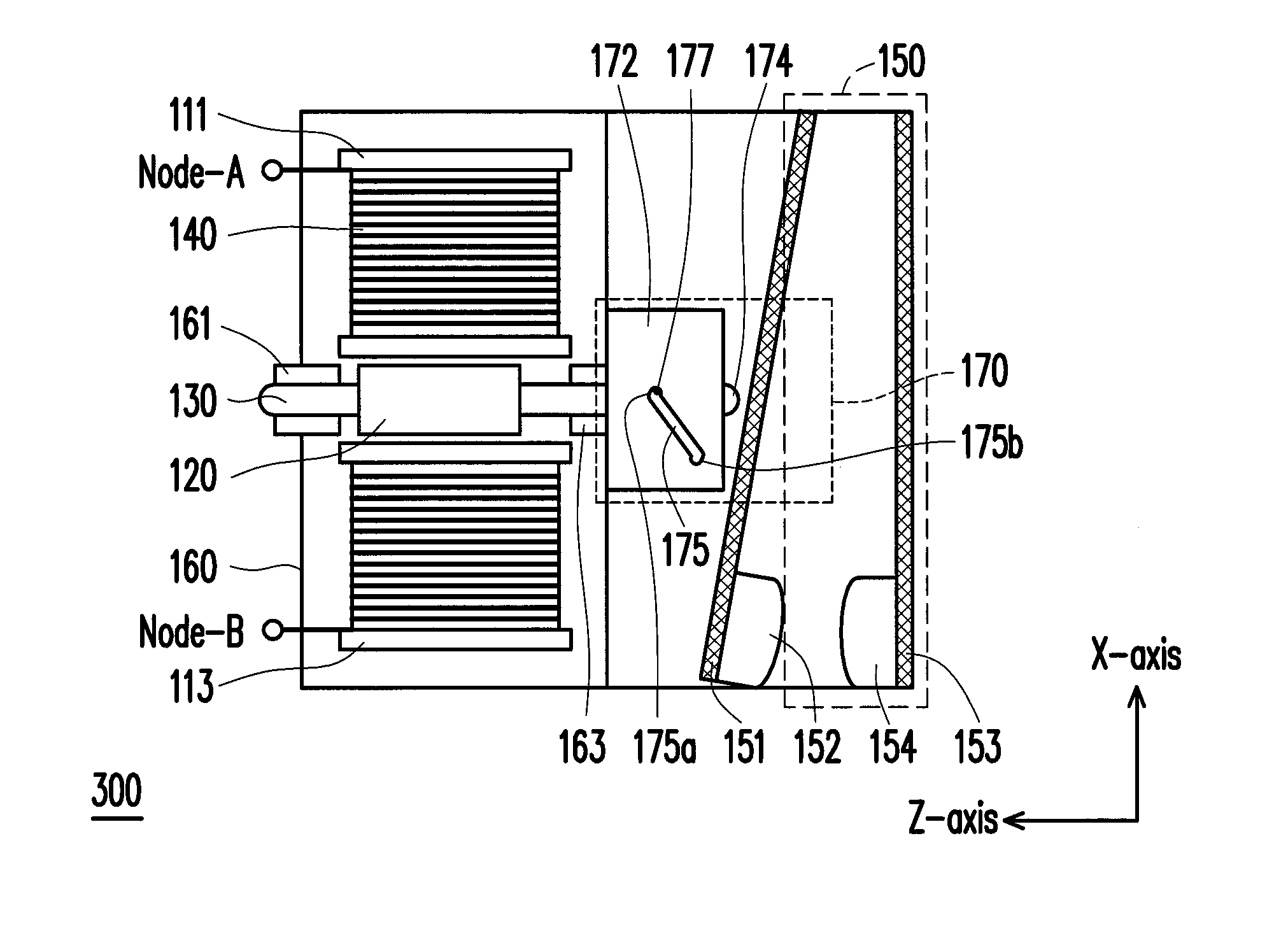
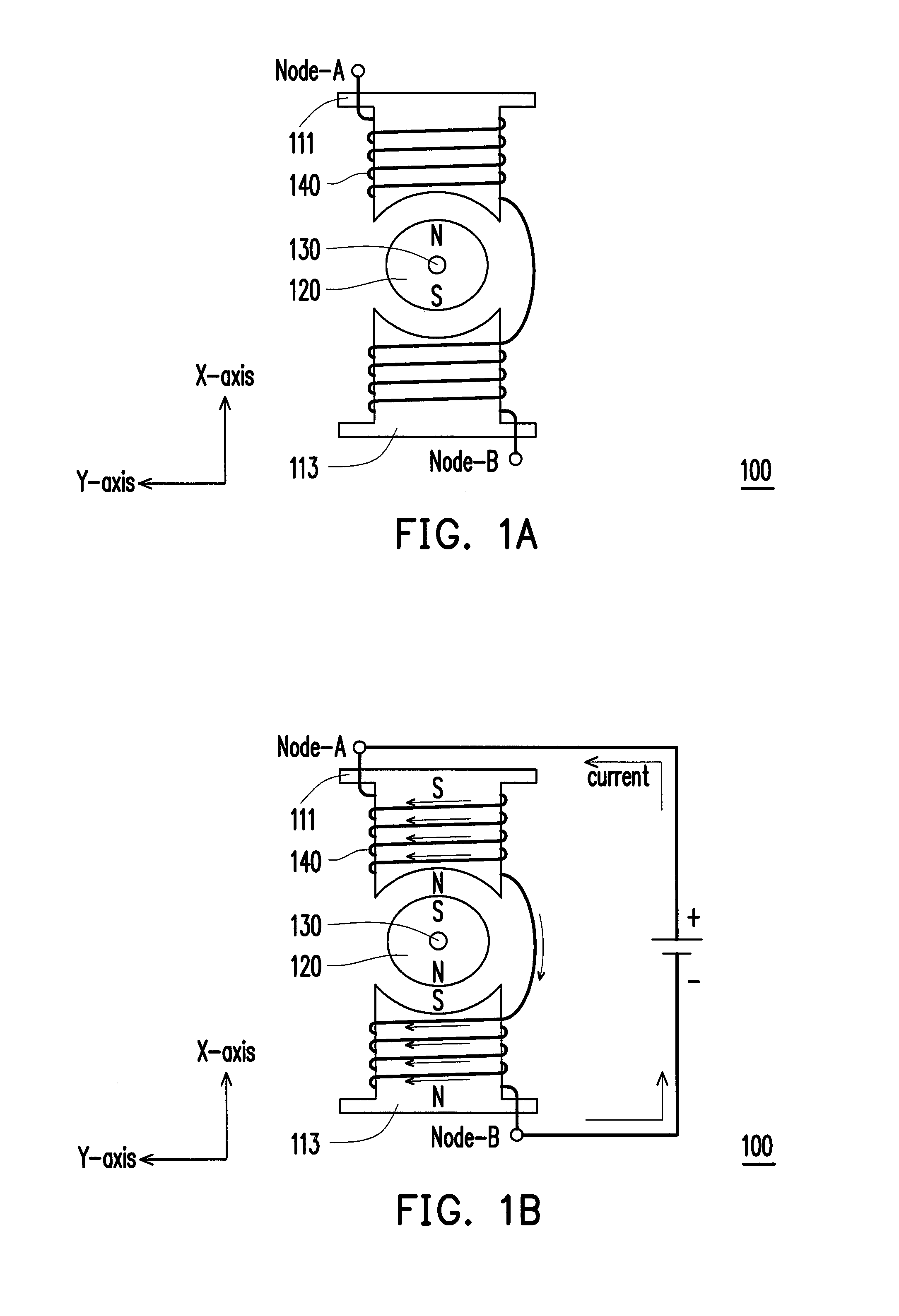
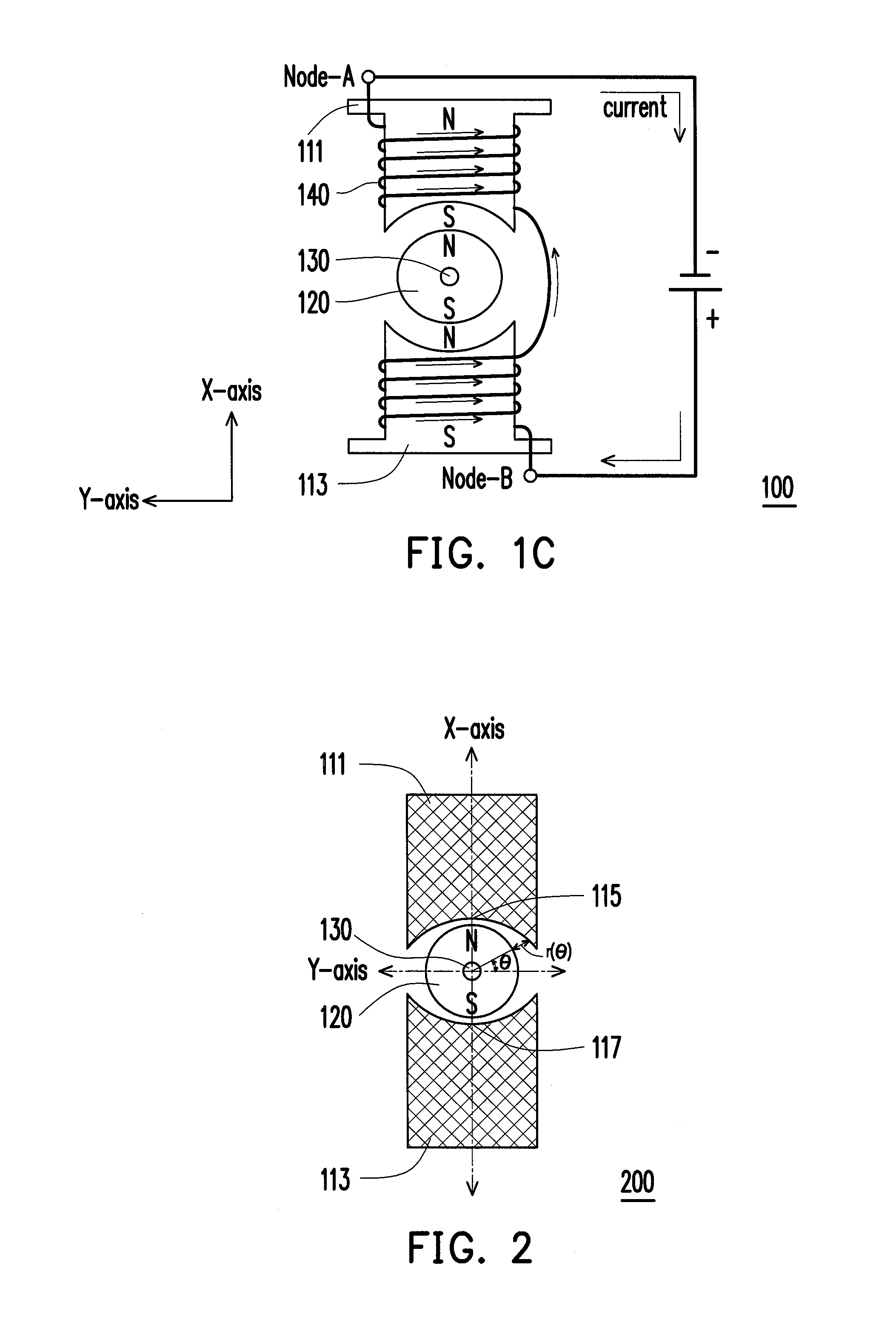
[0041]The coming figures will be described in different aspects which are presented as the space coordinate of X-axis, Y-axis, and Z-axis.

[0042]FIG. 1A, FIG. 1B and FIG. 1C are schematic views of the invention for a bistable latching mechanism 100 in the aspect of X-axis and Y-axis according to an embodiment of the invention. Please refer to FIG. 1A. The bistable latching mechanism 100 includes a first permeability material 111, a second permeability material 113, a cylindrical permanent magnet 120, a rotor shaft 130 and a coil 140.

[0043]The cylindrical permanent magnet 120 covers the rotor shaft 130 as the form of concentric circles, and the cylindrical permanent magnet 120 and the rotor shaft 130 move synchr...


PUM


Abstract

A bistable switching method and a latching relay using the same are provided. The latching relay includes a rotor shaft, a cylindrical permanent magnet, a first permeability material, a second permeability material, a coil, a hitting device and a contact unit. The method includes the following steps. While the coil is applied first direction currents, the rotor shaft rotates and to make the contact unit from the open state to the closed state or the contact unit keeps the closed state. After the first direction currents are turned off, the contact unit still remains in the closed state. Otherwise, while the coil is applied second direction currents, the rotor shaft rotates and to make the contact unit from the closed state to the open state or the contact unit keeps the open state. After the second direction currents are turned off, the contact unit still remains in the open state.

Description

REFERENCE TO RELATED APPLICATION[0001]This application claims the priority benefit of U.S. Provisional Application Ser. No. 61 / 378,394, filed Aug. 31, 2010. The entirety of the above-mentioned patent application is hereby incorporated by reference herein and made a part of this specification.BACKGROUND OF THE INVENTION[0002]1. Field of the Invention[0003]The invention generally relates to a bistable switching technology and more particularly to a bistable switching method and a latching relay using the same.[0004]2. Description of Related Art[0005]General mechanical switches are classified into manual switches and electrical switches. Since the manual switches are necessary to be controlled by human power, the manual switches are difficult to be used in an electrical system. Therefore, electrical switches are usually used instead. In an electrical system, a mono stable relay is usually used as an electrical switch. When using one of the states of the mono stable relay, extra power m...

Claims


Application Information

Patent Timeline
Patent Type & Authority Applications(United States)
IPC IPC(8): H01H51/22
CPCH01H51/2263H01H50/643
Inventor LIANG, CHIH-CHUAN
Owner LIANG CHIH CHUAN
Why Eureka
Try Eureka